4 reset state, 5 fault indicator, 3 shunt locations – Sensoray 618 User Manual
Page 6
Sensoray Model 618/619 Smart A/D
4
Configuration
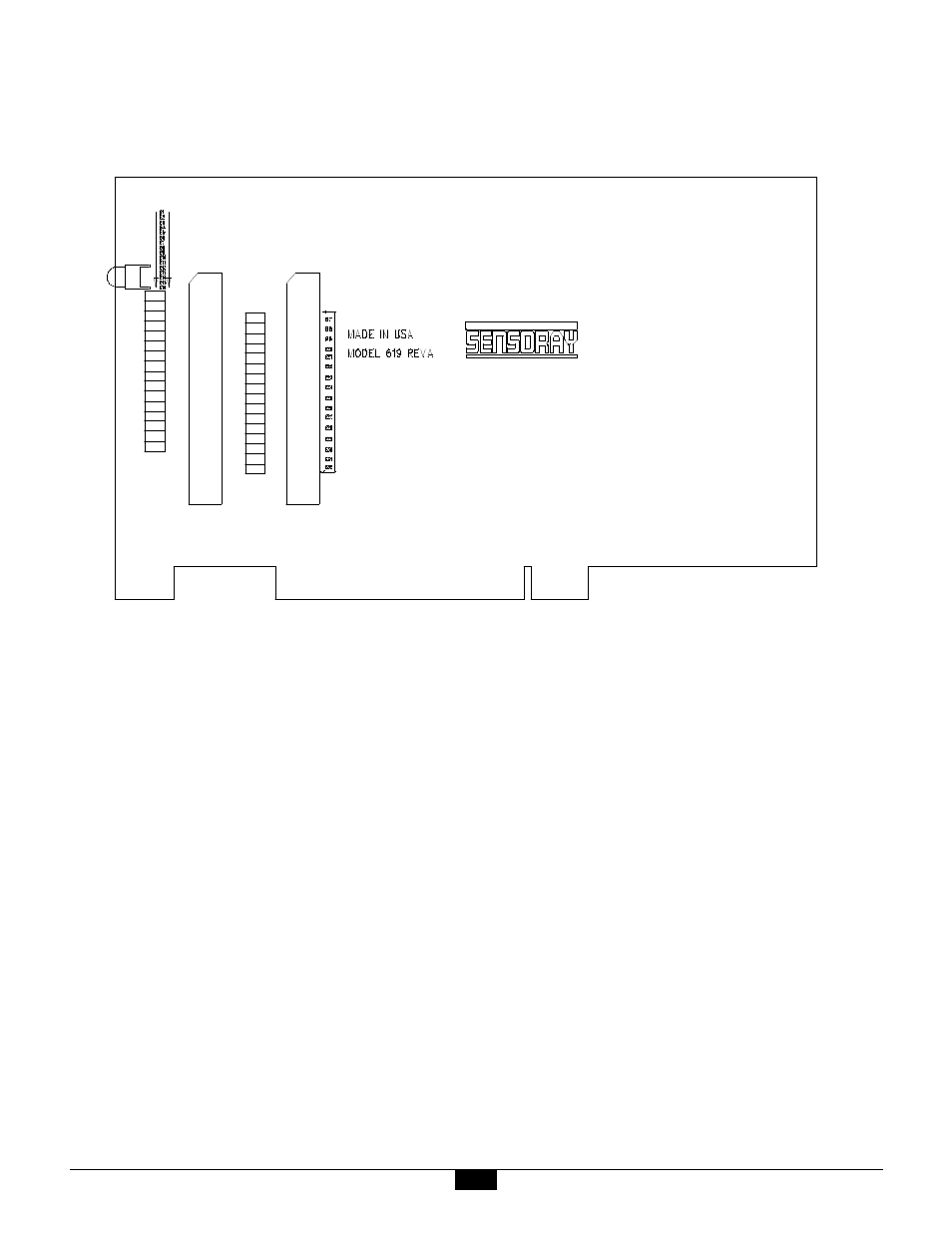
3.3 Shunt Locations
The diagram below shows the locations of hardware programming shunts on the Smart A/D board.
3.4 Reset State
At power-up, or after a soft reset (see Section 5.2.1) or a
system hard reset, the Smart A/D board is in its default
state as follows:
• Standard speed mode (22ms/channel) is selected.
• 60Hz rejection mode is active.
• All channels are enabled for scanning.
• Sensor data values are reset to zero. Sensor data is not
available immediately after a board reset. The
maximum elapsed time that must pass before new
sensor data becomes available is equal to 35 channel
slot times. Details of channel slot timing can be found
in Section 8.1
• Channels are configured for the 5-volt input range,
with 500µV resolution.
• Software filter constants are set to zero (disabled).
• Alarm threshold limit values are indeterminate.
• All channel alarms are disabled.
• All channels are programmed to fail high upon
open-sensor detection.
3.5 Fault Indicator
A red light-emitting diode (LED) on the Smart A/D
board is used as a status indicator. This LED is energized
under either of the following circumstances:
• A board reset is in progress.
• A board fault has been detected.
When the Smart A/D board is functioning normally, the
LED is energized for approximately one-half second in
response to a board reset, either hard or soft. In the case
of power-up and hard resets, this time period may be
longer as the result of a stretched hardware reset signal
on the system bus.
If the LED is persistently energized, there may be a
hardware fault on the A/D board. In this case, be sure to
check all sensor connections, board orientation and
seating, etc. before concluding that the board has a fault.
E1
E2
E3
E4
E5
E6
E7
E8
E9
E10
E11
E12
E13
E14
E15
E16
E17
E18
E19
E20
E21
E22
E23
E24
E25
E26
E27
E28
E29
E30
E31
E32
P2
P3