8 4-to-20 ma current loops – Sensoray 618 User Manual
Page 10
Sensoray Model 618/619 Smart A/D
8
Sensor Connections
If you are using a six-wire gage, you should connect the
gage’s excitation source and excitation sense leads
together at the I+ and I- terminals. Note that remote
sensing of the excitation signals is not supported.
The gage impedance seen by the Smart A/D excitation
source must be at least 120
Ω
to prevent automatic current
limiting. If the input impedance is less than 120
Ω
, a
resistor must be inserted in series with the gage excitation
terminals to prevent excessive excitation circuit loading.
Note that this will alter the mV/V rating of the sensor.
Gage output voltage must fall between -500mV and
+500mV under all load conditions, including any offset
caused by bridge imbalance. If the gage output voltage,
at 10V excitation, might exceed these input limits, it may
be necessary to configure the sensor channel for voltage
input and supply external excitation to the gage.
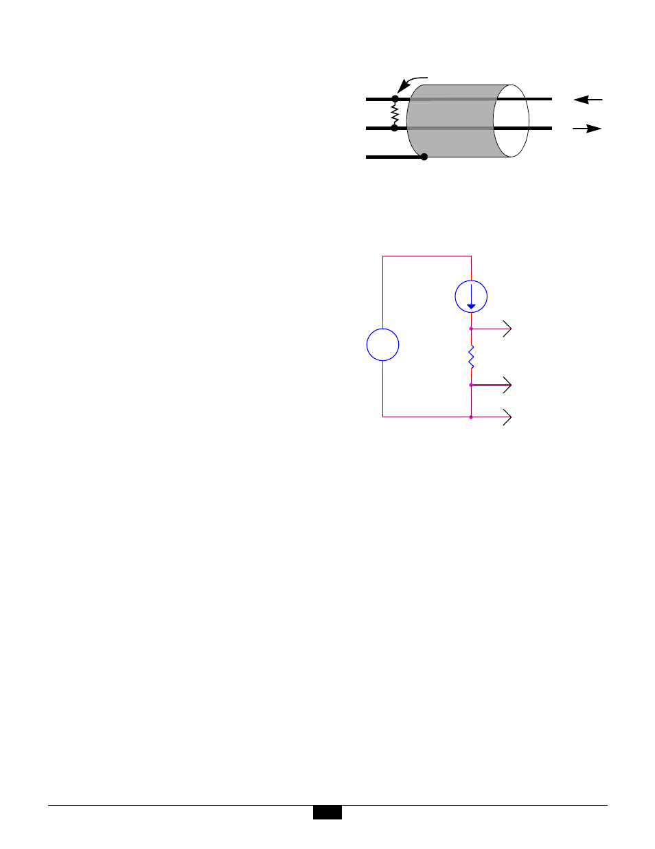
4.8 4-to-20 mA Current Loops
The Smart A/D supports 4-to-20 mA current loop inputs
on any channel, subject to two constraints:
1. A 250
Ω
, 0.01% resistor must be installed as shown in
the following diagram. This resistor, which converts
the loop current to a voltage, is available as an option
for the Smart A/D; order Sensoray part number
7408R.
2. Only the grounded end of the current loop may be
connected to a sensor channel. This ensures that the
common-mode voltage will not exceed Smart A/D
input limits.
4-20 mA current loop connection
It is important to note the Smart A/D does not provide
excitation for current loops. Current loops must be
energized from an external power source, such as the
isolated 12V power supply in the following schematic:
If the external power source is not isolated (i.e., its
negative output terminal is connected to the backplane
power supply return), you should not connect to the S
terminal as shown in the above diagram, as a potential
ground loop would be created. In such a case, leave the S
terminal disconnected and connect to the V+ and V-
terminals only.
V +
V –
S
Sensoray P/N 7408R
(+)
(–)
+
-
12V
POWER
SUPPLY
SENSOR
7408R
V+
V-
S