Desa DVF32TMHST User Manual
Page 11
- 10 -
For more information, visit www.desatech.com
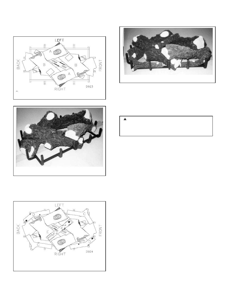
9. Place logs “B” as shown in Figures 25 and 26. Lift the
propped up end of log “A” that is propped up and place log
“B” under it. At the same time, the other side of log “B” is
placed over the other log “A”. Repeat procedure for the other
log “B”.
10. Take twigs “C” (shaped like a “Y”) and place them as
shown in Figures 27 and 28.
11. Take twigs “D” (bent twig) and place them as shown in
Figures 27 and 28.
12. Place twig “E” across the top of logs “B” shown in
Figures 25 and 26.
13. When finished installing the logs, close the glass doors
securing the four (4) spring loaded latches.
14. Replace the louvers in reverse order with the grilles
pointing in the down position.
GLASS DOOR CLEANING AND REPLACEMENT
When cleaning or replacement is necessary, refer to the
following steps.
NOTE: Before proceeding make sure unit is completely cool.
CLEANING GLASS DOOR
• Remove the top and bottom louvers and the screen
assembly. (see figure 29).
• Undo the four spring door latches (see figure 20).
• To install or replace items removed, simply reverse these
procedures.
REPLACING GLASS DOORS
• If replacement of the entire assembly (frame and glass
assembly) is required, carefully remove the six (6) screws
located on the hinge at the left end of the glass door while
holding the frame assembly to prevent it from falling and
causing injury.
• Remove glass assembly retainer brackets by removing
two screw nuts located at the top and bottom of the glass
door, frame (see figure 30). Carefully lean the glass away
from the frame and remove for replacement.
• Be sure that the gaskets and panels are squarely placed in
the frame and that all brackets and screws are firmly
secured.
WARNING: Improper installation, adjustment,
alteration, service or maintenance can cause injury or
property damage. Refer to this manual for assistance.
Consult a qualified installer for additional information.
Figure 25 LOG “B” PLACEMENT
Figure 26 LOG “B” PLACEMENT
Figure 27 LOGS “C”, “D” AND “E” PLACEMENT
Figure 28 LOGS “C”, “D” AND “E” PLACEMENT