Dv4 back panel, Dvi input, Dvi output – RGBLink DV4 User Manual User Manual
Page 22: 3、5: outputs of sending card, 4、6: dvi input port of sending card, 7、8: power interface and switch, Hardware orientation
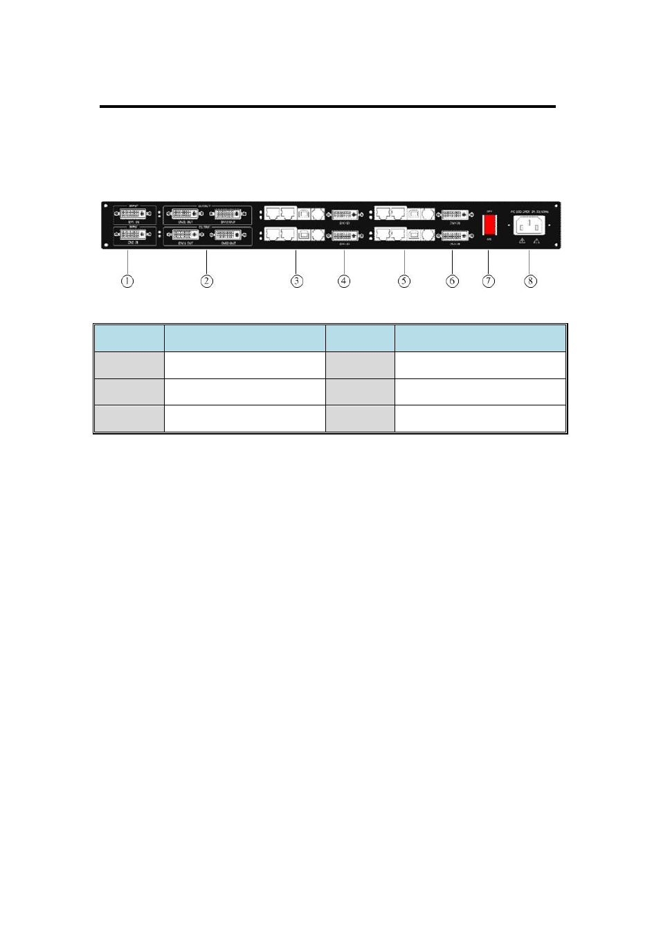
2. Hardware Orientation
DV4 Back Panel
DV4 User Manual 22
The figure below illustrates the professional interface and control signals
of DV4 back panel:
NO
INTERFACE
NO
INTERFACE
1
DVI Input
4、6
DVI Input Port of Sending Card
2
DVI Output
7
Switch
3、5
Outputs of Sending Card
8
Power
1: DVI Input
DVI input. Input the video signal from computer, DVI signal generator.
Connect to the same DVI interface.
(This Connection does not support hot-plugging).
2: DVI Output
Connect to the input port of sending card, output DVI signal to DVI input
port of sending card.
3、5: Outputs of Sending Card
Connect to LED screen.
4、6: DVI Input Port of Sending Card
Connect to DVI output, and receive the signal from DVI output.
7、8: Power Interface and Switch
AC 100-240V 3A 50/60Hz IEC-3 power interface.
Currently, DV4 is only available for Linsn 801/802, Nova MSD300,
Colorlight Q7 and DBstar Q2011 sending card.