RGBLink MSP 215A User Manual
Page 5
MSP 215 User Manual
RGB-RD-UM-M215E001
2
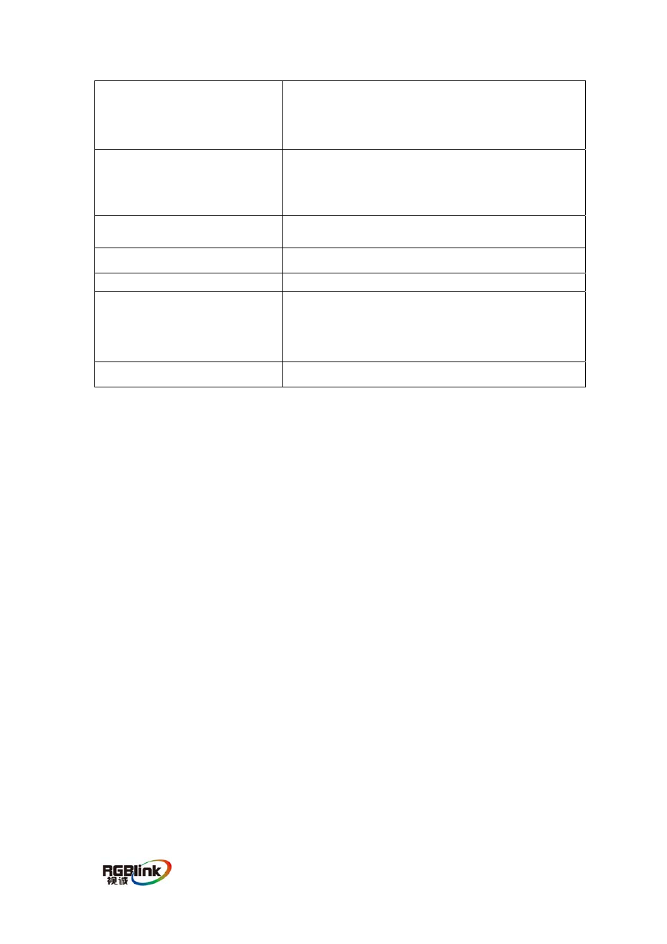
Local Video and Audio
One High Density DB15 Female;
One 3.5mm female stereo audio jack
Connect with User
Two High Density DB15 Female;
Two 3.5mm female stereo audio jack
Subunit Connector
RJ45(connect local unit and remote unit)
Cable Type
Category 5/5e/6 UTP
Power Adapter
2 X DC 9V/1A
LEDs
Local unit :
One for power, one for Video, one for Audio
Remote unit :
One for power, one for Video, one for Audio
Dimensions
108 X 94 X 26 mm
5.0 INSTALLATION
Installing the Local unit
(1) Connect a female-to-male HD-15 VGA cable to the VGA Out port on the local
computer. Connect the opposite end to the male 15HD port on the Local unit.
(2) Connect a male-to-male headphone audio cable to the Speaker Out port on the
local computer. Connect the opposite end to the audio in port on the Local unit.
(3)If you wish to use local displays and speakers, connect them to the female 15HD
port and the Speaker port on the Local unit.
(4)Connect the Ethernet cable connection for Remote Unit to the RJ-45 connector
labeled with REMOTE I/O on the Local unit. The cable such as CAT5,CAT5E,CAT6
can be used, both terminal of the cable should be made according to EIA/TIA568B
standard.
(5)Connect the power adapter into an appropriate power source and plug the
opposite end into the power connector on the Local unit. The POWER LED will
light.
Installing the Remote unit
(1)Connect the data cable from the display(s) to the opposite side of the Remote
Unit,marked with monitor. You may choose to have either one or two displays at the
remote location connected to the Remote Unit.
(2) Connect one or two sets of speakers to the speaker ports marked with speaker
on the Remote unit.
(3)Connect the Remote Unit to the Ethernet cable connection from the Local unit,
marked with REMOTE I/O. The cable such as CAT5,CAT5E,CAT6 can be used, both
terminal of the cable should be made according to EIA/TIA568B standard.