Research Concepts RC1500 User Manual
Page 9
Antenna Setup
9 RC1500B Quick Start Guide
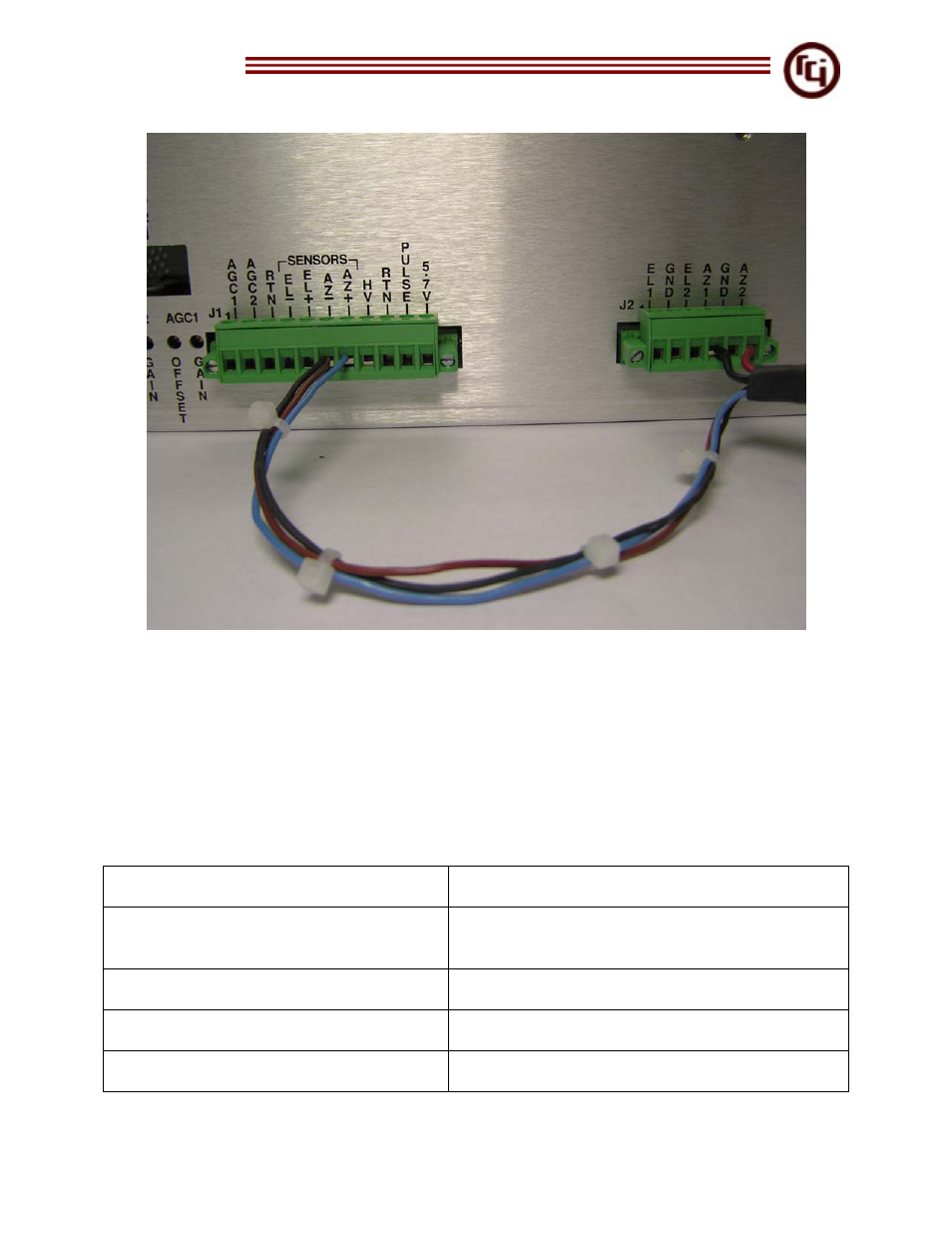
Figure 8 – Connection at RC1500 Back Panel / Strain Relief
Figure 8 shows the proper inches of cable to protect against cable stress. The larger
16-gauge cables are cut 5 ½ shorter to take any type of stress caused by the controller
being moved or the cables stretched. The sensor AZ- should have the brown and drain
wires connected to it. The drain wire appears black in this picture due to the heat shrink
on it which protects against short circuiting.
11. Insert Motor and Sensor conductors into the J1 and J2 Molex connectors. See
Table 1.
Table 1
J1: 6 AZ – (sensor connection)
22 AWG Brown
J1: 6 AZ – (Drain)
22 AWG Bare Drain wire (Cover with heat
Shrink)
J1: 7 AZ + ( sensor connection)
22 AWG Blue
J2: 6 AZ2 (Motor Drive Connection)
16 AWG Red
J2: 4 AZ1 (Motor Drive Connection)
16 AWG Black