Research Concepts RC1500 User Manual
Page 10
Antenna Setup
RC1500B Quick Start Guide
10
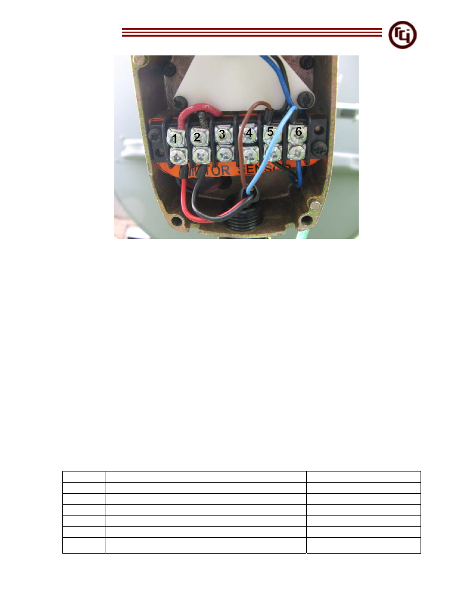
Figure 9 – Wiring Connection at Actuator
Table 2 explains the connections at the actuator. The connections are labeled 1-6. Do
not connect the drain wire at the antenna. Having the drain wire connected at the
antenna can cause a ground loop resulting in runaway errors.
Insulate drain wire to prevent it from making contact with earth ground.
12. At the actuator end of cable, cut the outer jacket back about 3 ½ inches, exposing
the two sub-cables. Remove the sub-cable jacket from the 16 AWG conductors. Also
remove the foil from position feedback conductors.
13. Strip all wires ¼ inch at the tip to allow insertion into screw terminal inside of the
actuator head. Tin or use wire ferrels on each tip for best results.
14. Cut the yellow and bare drain wire at the base. Use heat shrink to cover break.
15. Add a 1 inch piece of heat shrink (3/16 inch diameter) around outer jacket to cover
the first cut made at 3 ½ inches.
16. Run cable through hole in actuator head and insert conductors into screw terminals.
Refer to Figure 9 and Table 2.
Actuator Signal
Cable
1
+ Motor Drive Connection
16 AWG Red
2
- Motor Drive Connection
16 AWG Black
3 No
Connection
4 No
Connection
5
AZ – Reed Sensor Connection
22 AWG Brown
6
AZ + Reed Sensor Connection
22 AWG Blue