Research Concepts RC1500 User Manual
Page 8
Antenna Setup
RC1500B Quick Start Guide
8
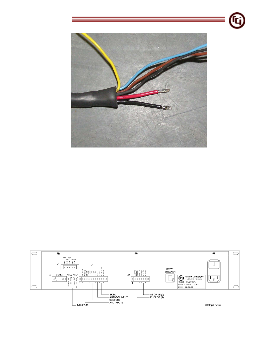
Figure 6 – Stripped Sub-cables
3. Cut the two red and black 16 AWG conductors to 2 ½ inch length.
4. Cut the drain, brown and blue 22 AWG conductors to 7 inch length.
5. Cut the yellow 22 AWG conductor away at the base. This wire is not needed.
6. Strip every wire ¼ inch at the tip to allow insertion into the J1 and J2 Molex
connectors.
7. Add 3/64 or 1/8 inch in diameter piece of heat shrink to drain wire. Make the heat
shrink 6 ¾ inches long. Slide heat shrink over entire drain wire to avoid a short
circuit, leaving ¼ inch of conductor exposed at the tip. Use heat gun to set heat
shrink.
8. Add a 1 inch piece of heat shrink (3/16 inch diameter) around outer jacket to
cover the first cut made at 9 ¼ inches.
9. For best results, either tin the end of each conductor or use wire ferrels.
10. Place cable ties for added strain relief as shown in Figure 8
.
Figure 7 – RC1500 Back Panel Diagram