Wiring – Remotec ZTS-110 V3.05 User Manual
Page 5
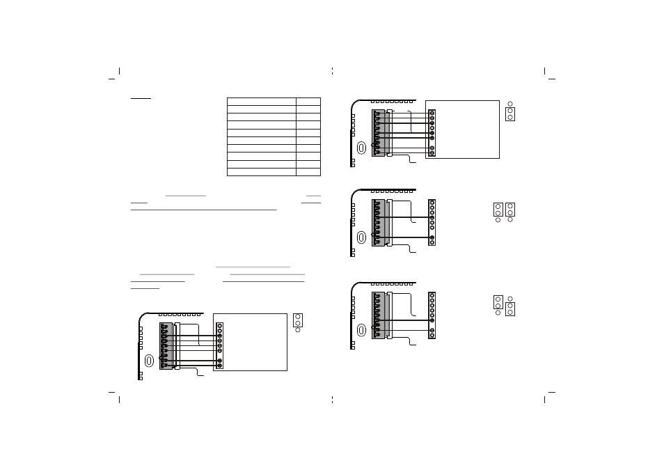
Figure 5. Heat pump HVAC system wiring
Figure 6. Non-heat pump 2-wires system wiring
Figure 7.Heat pump 2-wires system wiring
Thermostat should be powered by batteries and support heating control only.
Thermostat should be powered by batteries and support heating control only.
For heat pump output, there is a 3 minutes off time for heat pump protection.
7
8
Wiring
- Be sure the operation mode is OFF
and Fan selection is Fan Auto
- Wire the proper cables at the terminal
block according to the circuit diagram
- Afterward, push all cables back into
the wall
- Do not use metal conduit or of cable
provided with a metal sheath
- Recommends adding fuse or
protective device in the line circuit
Important!
If you will be powering the ZTS-110 with 24Vac:
Connect the "24Vac Common" (typically the black wire/terminal) and "24Vac
Power" (typically the Red wire/terminal) from the HVAC system to the ZTS-110
HVAC System terminal block "C" and "RH" or "RC" terminals (see the following
explanation, these may be jumpered together).
Common or Split Transformer Systems:
Most HVAC systems have a common heating and cooling transformer. You must
insert a jumper wire to tie the RH and RC inputs together for this configuration. If
you have a system with separate heating and cooling transformers, do not insert a
jumper wire between RC and RH.
When wiring split systems, wire the heating systems "24Vac Power" (red wire) to
the ZTS-110 "RH" terminal, and wire the cooling systems "24Vac Power" to the
ZTS-110 "RC" terminal. Also wire the cooling systems "24Vac Common" to the
ZTS-110 "C" terminals.
Note: Do not split RC/RH for Heat Pump systems!
Figure 4. Non-heat pump (Standard Gas or Electric) HVAC system wiring
Terminals
Cool changeover (heat pump)
Heat changeover (heat pump)
2nd Stage heater
1st Stage heater
Fan
Compressor
24Vac Common
24Vac Power for Cooling
24Vac Power for Heating
Symbol
O
B
W2
W1
G
Y
RC
RH
C
Standard HVAC System
nd
W2 - 2 stage heater
st
W1 - 1 stage heater
G - Fan
Y - Compressor
R - 24Vac Power
C - 24Vac Common
O
B
W2
W1
G
Y
RC
RH
C
Brown
White
Green
Yellow
Red
Black
Heat Pump HVAC System
O - Cool changeover (heat pump)
B - Heat changeover (heat pump)
nd
W2 - 2 stage heater
G - Fan
Y - Compressor
R - 24Vac Power
C - 24Vac Common
O
B
W2
W1
G
Y
RC
RH
C
Brown
Green
Yellow
Red
Black
Blue
Orange
ELECTH
HPUMP
J2
ELECTH
HPUMP
J2
ELECTH
HPUMP
J2
Y - Compressor
R - 24Vac Power
O
B
W2
W1
G
Y
RC
RH
C
Yellow
Red
HG
HE
J1
HG
HE
J1
ELECTH
HPUMP
J2
st
W1 - 1 stage heater
R - 24Vac Power
O
B
W2
W1
G
Y
RC
RH
C
White
Red