Remotec ZFM-80 User Manual
External switch, Warning, Introduction
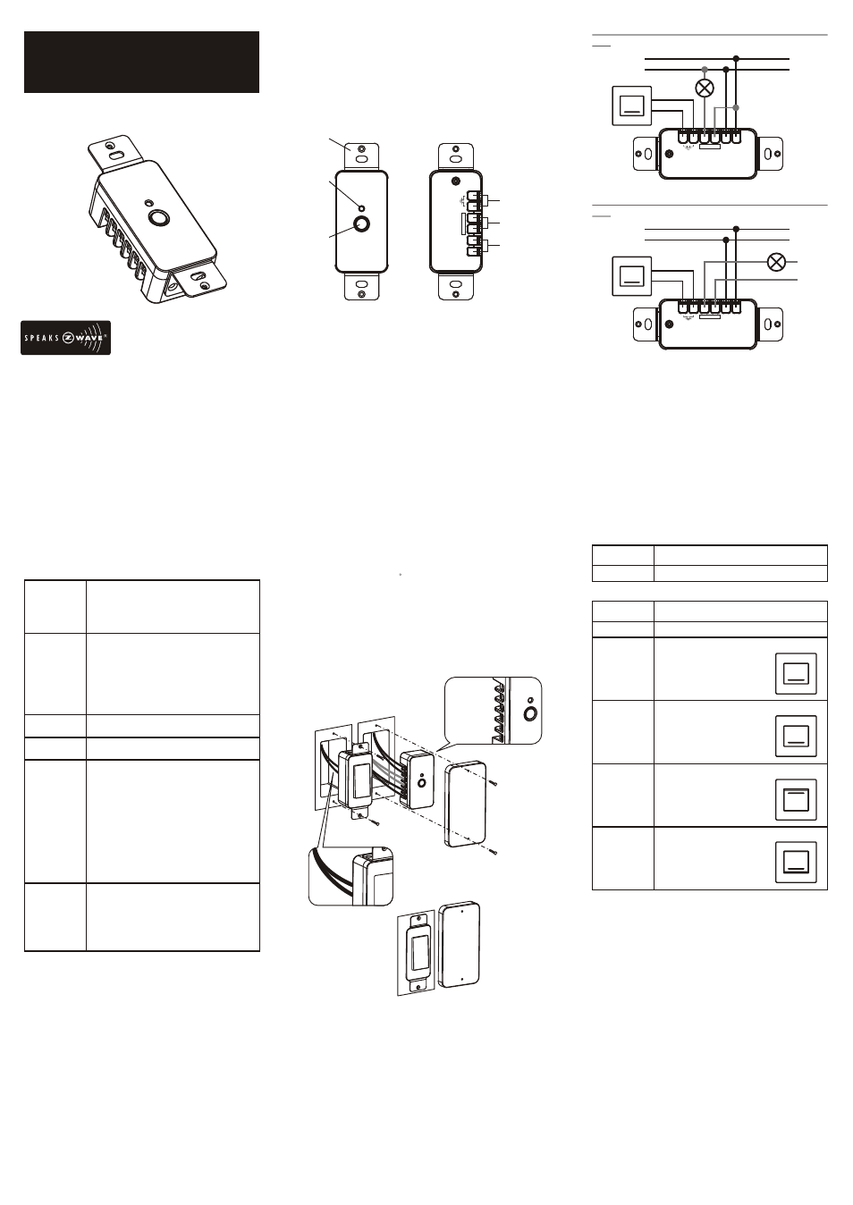
Single switch (connected with input AC power source for the
load)
External Switch
ZFM-80US provides an option to user that can add an
external switch to control the On/Off function. ZFM-80US
can be placed into the switch box with external wall
switch cover. User can configure the external switch type
through the configuration command
Configuration Command for External
Switch
Advanced function "Conditional trigger
for Fail Safe Application"
ZFM-80US provides an advanced function "Conditional trigger
for Fail Safe Application". It can turn on or turn off the relay if
ZFM-80US has not received any Z-Wave commands from a
specified Z-Wave Node ID and within a specified period. For
example: Z-Wave gateway can monitor a Z-Wave device status
and power on equipment if this Z-Wave device is out of service.
Figure 1
Single switch (connected with an external power source for the
load)
Figure 2
Warning
The resistive household appliance connected into the Z-Wave
controlled outlet on this module must not exceed 230Vac 10A or
120Vac 15A.
RELAY
(LOAD
)
N
L
L
N
RELAY
(LOAD
)
N
L
L
N
External switch
External
power source
Load
Load
L'
N'
Introduction:
Thank you for choosing ZFM-80US Z-Wave control product. Our
Z-Wave enabled product allows user to remotely control resistive
household appliance, and make home control easy at low
installation / maintenance cost. You may begin with a few Z-
Wave enabled devices or build up a complete home automation
system with our products.
The ZFM-80US Fixture Switch Module is a Z-Wave enabled
device and fully compatible with any Z-Wave enabled network. It
allows remote On/Off control of specified resistive household
appliance. Each fixture switch module is designed to act as a
repeater, which will re-transmit the RF signal to ensure that the
signal is received by its intended destination by routing the signal
around obstacle and radio dead spots.
Glossary
Key Features:
-
High output power
-
Remote ON/OFF control via the Z-Wave controller
-
Manual ON/OFF control with the front panel push button
-
Support External ON/OFF key connects to the module
- Advanced function
Conditional trigger for "Fail Safe Application"
-
Support Network Wide Inclusion (NWI) and Explore Frames
-
Screw terminals for wires connection
-
Flexible mounting structure - mount inside gang box or any
place
Wireless Control
ZFM-80US/DA065
Z-Wave Fixture Switch Module
USER MANUAL
Device /
Light /
Node
Z-Wave
Network
Inclusion
Exclusion
Network
Wide
Inclusion
(NWI)
Association
Devices, lights and nodes are all terms
to describe an individual Z-Wave device.
These are all interchangeable when
setting up your Z-Wave network.
A collection of Z-Wave devices is controlled
by primary and secondary controllers
operating on the same system.
A Z-Wave network has its own unique ID
code so that controllers not in the network
can not control the system.
Add a Z-Wave device to the network.
Delete a Z-Wave device from the network.
Network Wide Inclusion (NWI) enables
both end-user friendly, Plug and Play like
Z-Wave network installation as well as
professional installation scenario where
the inclusion process in terms of time will
be reduced significantly. NWI is a feature
supported by a new frame type named
Explorer which enables the Z-Wave
protocol to implement Adaptive Source
Routing.
Association is used to organize nodes in
different groups allowing the device to
identify the nodes by a group identifier.
The groups can also be copied to other
devices.
()
RELA
Y
LOAD
N
L
Product Overview:
A
B
C
D
E
F
Mount
Status LED
ON/OFF/PROG Push button
External switch (S/W)
Z-Wave controlled output (isolated relay, RL)
AC input (L = terminal for Live lead;
N = terminal for Neutral lead)
A
D
B
C
E
F
Installation:
DANGER! SHOCK HAZARD. Read and understand these
instructions before installing. This device is intended for
installation in accordance with the National Electric code and
local regulations in the United States, or the Canadian Electrical
Code and local regulations in Canada. It is recommended that a
qualified electrician perform this installation.
For indoor use only in a dry location. Retain instructions for future
use.
Step 1
WARNING: To reduce the risk of fire or electric shock,
install in a controlled environment relatively free of
contaminants. To avoid fire, shock, or death; turn off
power at circuit breaker or fuse and test that power is off
before wiring!
Step 2
Identifying your wiring application: refer to figure 1
and 2
NOTE: If the wiring in the wall box does not resemble
any of above configurations, consult a qualified
electrician.
Step 3
Connecting wires: refer to figure 1 or 2 and connect
the wires with correct symbols.
Use at less
75 C copper wire only and the stripped
wire end's length must be 9mm. The tightening torque
must be 3.5lb-in. (Make sure all wires are firmly fixed at
all terminals)
CAUTION : Risk of Electric Shock More than one disconnect
switch may be required to de-energize the equipment before
servicing.
S/W
S/W
RL
RL
L
N
External Switch
Parameter
Number
Set External switch type
Definitions
1 (0x01)
Parameter
Value
Disable External switch
Definitions
0 (0x00)
1 (0x01)
2 (0x02)
3 (0x03)
4 (0x04)
Type A:
Tact switch (normal open)
Type B:
Tact switch (normal close)
Type C:
Rocker switch
(short = On; open = Off),
default
Type D:
Rocker switch
(short = Off, open = On)
Example:
Example:
Example:
Example:
External switch
S/W
S/W