REMKO EFS 25 User Manual
Page 13
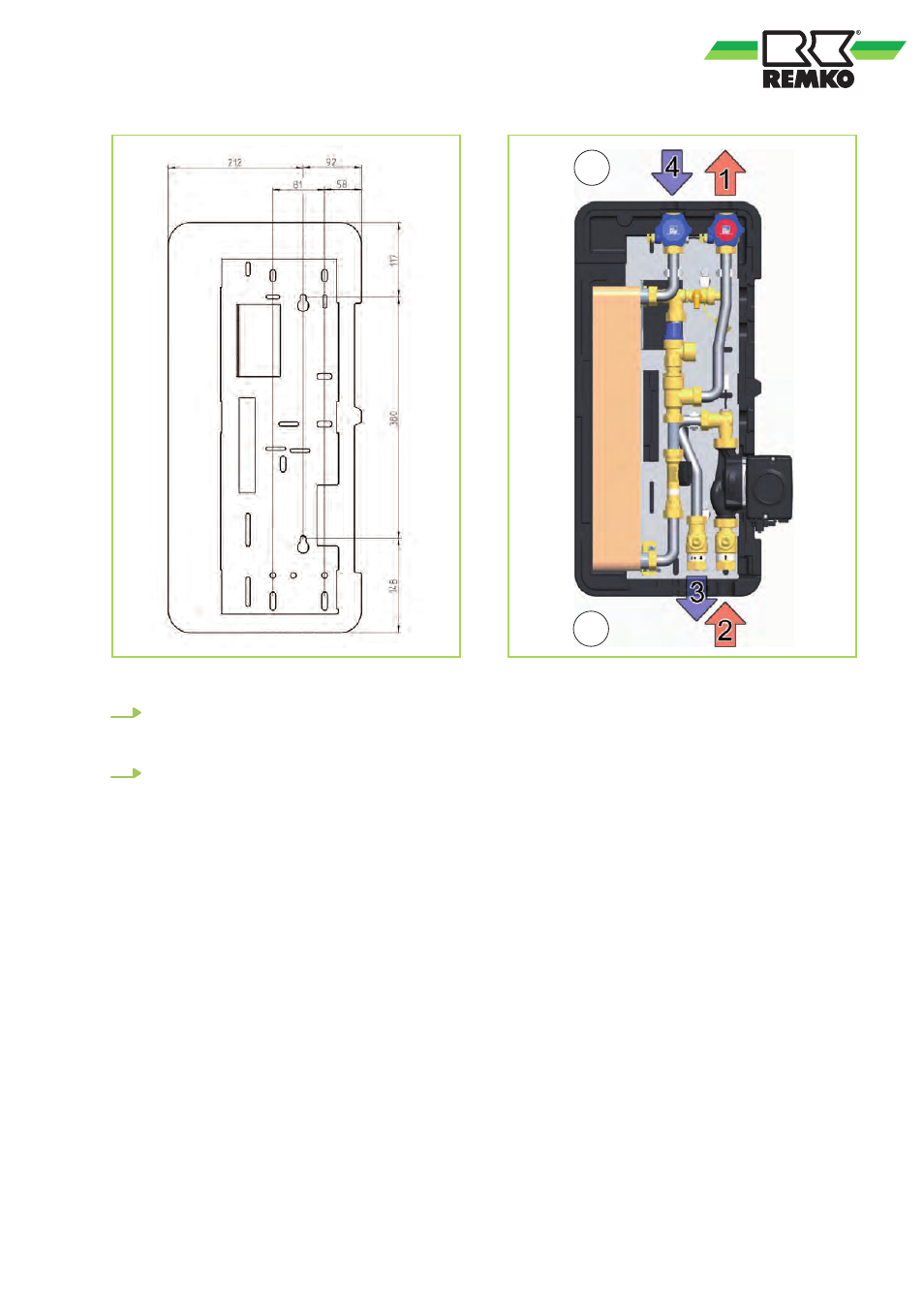
Fig. 4: Distance between the holes
6.
Hang the fresh water module onto the
screws. Tighten the screws so that the insu-
lation on the sides is flush to the wall.
7.
Connect the pipes of the fresh water module
to the system in accordance with Fig. 5.
1. Secondary side:
Hot water outlet,
Connection ¾" AG, flat-sealing
2. Primary side:
Inlet from buffer tank, ¾" IG,
Piping at least DN 20 22 x 1 mm,
recommended DN 25 28 x 1.5 mm
3. Primary side:
Return flow to buffer tank, ¾" IG,
Piping at least DN 20 22 x 1 mm,
recommended DN 25 28 x 1.5 mm
4. Secondary side:
Cold water inlet,
Connection ¾" AG, flat-sealing
A
B
Fig. 5: Piping of the fresh water station
A: Pipe distance from the wall
(secondary) = 107 mm
B: Pipe distance from the wall (primary) = 67 mm
13