Electrical connection – REMKO RWK 260 User Manual
Page 14
14
Attaching the wall mount
The units must be attached with suitable screws and
dowels. The attachment points are displayed in the fol-
lowing figure.
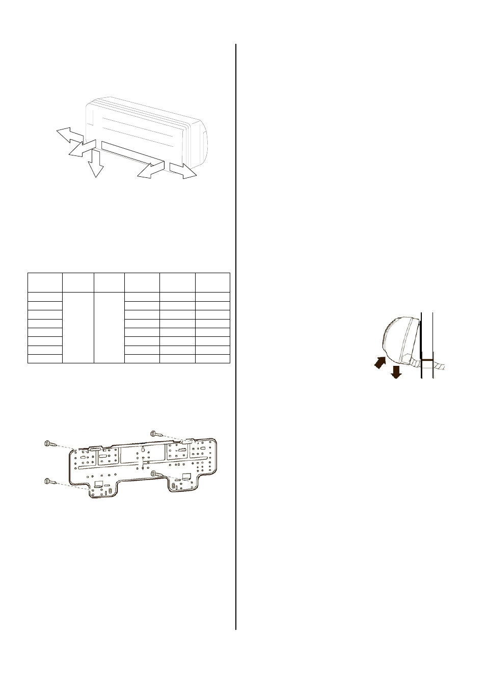
Lead-through options
Prior to installation, take a look at the various options
for lead-throughs of the refrigerant and condensation
pipes and control lines (see figure below).
1 Opening on the wall right
2 Opening through the wall rear
3 Opening on the wall bottom
4 Opening through the wall rear
5 Opening on the wall left
Assembling the indoor unit
Install the indoor unit as follows:
1. The required pipe diameters are provided in the
"Technical Data” table of the outdoor unit.
Only use refrigerant pipes with refrigerator quality.
2. Decide which drainage option you want to use for
the indoor unit and cut the refrigerant connection
pipe accordingly.
13. Lay the refrigerant pipes from the indoor unit to the
outdoor unit.
14. Connect the refrigerant pipes to the outdoor unit as
described in the operating instructions of the out-
door unit.
Prior to performing any work on the unit, it must
be unplugged from the power supply and secured
against being inadvertently switched on!
Electrical Connection
A 4-wire control line must be led from the indoor unit to
the outer unit. Cooling and heating units require a 6-wire
control line.
All electrical installations may only be performed by
authorised personnel in line with the relevant regulations.
Local guidelines for operation as well as the require-
ments established by local energy supply companies
must be observed for setup and initial operation.
3. When assembling the unit, observe the bending ra-
dii of the refrigerant pipes and never bend the hose
in the same place twice. This may cause the pipe to
become brittle or crack.
4. Remove the preinstalled swivel nuts of the units.
5. Keep in mind that the indoor units have been filled
with dry nitrogen as a sealant at the factory.
The pressurised nitrogen is released when the
swivel nuts are loosened.
6. When assembling the unit, only use tools suitable
for low temperature ranges.
7. Work with the pipes as described in the operating
instructions of the outdoor unit.
8. Insulate the installed refrigerant pipes including the
connector against heat.
9. Only use insulation hoses sealed against diffusion
that are suitable for this temperature range.
10. If you have selected option 2 or 4 (drainage through
the wall), guide the condensation water and control
line through the wall lead-through to the indoor unit.
If you also need a condensation pump, it must be
installed beforehand.
11. If, due to structural design conditions, it is not possi-
ble to guide the condensation pipe through as well,
make sure that the condensation can drain freely at
all times.
12. Hang the indoor unit leaning
slightly to the back in the pre-
viously assembled wall mount
and press the bottom of the
unit into the mount.
Do not damage the pipes and
ensure that they are in the
correct position.
3
4
2
1
5
Connecting the refrigerant pipes
A fitting may need to be installed on the indoor units to
extend or reduce the pipes. These screws are supplied
with all indoor units in the series.
Injection
pipe
Suction
pipe
RWK 260 RWK 350 RWK 520
RKM 610
3/8 “
1/2 “
Kit 1
-
-
RKM 613
-
Kit 1
-
RKM 620
-
-
Kit 1
RKM 710
Kit 1
-
-
RKM 713
-
Kit 1
-
RKM 720
-
-
Kit 1
RKM 810
Kit 1
-
-
RKM 813
-
Kit 1
-