Pennco 3KW0.60 User Manual
Page 19
19
MAIN AIR VENT: (not provided)
Before filling system with water, there is air in the pipes
and radiation units. Some air is trapped as system filled.
Eliminate most of this air through air vents on radiation
units. Main air vent speeds and simplifies process. Install
main air vent on highest point in supply main.
AUTOMATIC FILL VALVE (not provided)
For safe, efficient operation, fill hot water system with
water. Adding new water, when needed can be done
manually (by use of hand valve in water supply line).
Requires regular attention to system’s needs. Automatic fill
valve or pressure reducing valve accomplishes this without
attention. Install in supply line on hot water boilers only.
Valve operates through water pressure differentials. Does
not require electrical connection.
BURNER SOLENOID VALVE (provided)
Beckett oil burners use standard solenoid valve. Upon
burner shut down, standard solenoid valve stops flow of
oil to nozzle. Without solenoid valve, oil pump continues to
pump oil to burner nozzle until burner motor winds down
below pumps cutoff speed.
LIMIT CONTROL (provided) Refer to manufacturer
instructions provided with limit control
Water temperature limit control in limit is adjustable and
may be set: as low as 140°F, as long as return water
temperatures to boiler are no less than 120°F, or as high
as 220°F and as long as boiler and heating system have
adequate circulation to remove heat from boiler otherwise
steam may be created in boiler. Refer back to SYSTEM
PIPING section for more information.
DRAIN VALVE (provided)
Drain valve is manually operated valve, provides means of
draining all water from boiler and heating system. Install in
reducing tee where return line enters boiler.
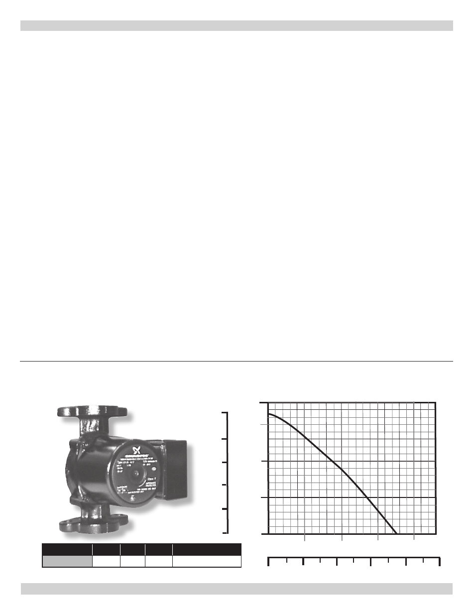
CIRCULATOR (provided)
Forced hot water system requires circulator. Separate
circulator or zone valve is required for each zone, if there are
two or more zones. Circulator must have capacity to provide
circulation required by heating system. Connect circulator
to supply main and wired into boiler’s electrical system. See
System Piping section for piping configurations with circulator
located on supply main piping using zone circulators or zone
valves. Piping arranged with zone circulators and no bypass
piping, circulator provided with boiler may be used as zone
circulator. Both piping arrangements allow circulator to pump
away from expansion tank and show how piping should be
arranged to allow heating system to be easily purged of
air. Circulator can be installed on return side of boiler if
preferred.
The pump curve for the furnished Grundfos UP 15-42 F pump is shown below:
Model
Watts Volts Amps
Capacitor
UP 15-42F
85
115
0.74
10µF/180V
15
10
5
0
5
4
3
2
1
m H
ead
1
2
3
4 5
US GPM
5
10
15 20
m /h
3
H
ead (f
eet)
EQUIPMENT AND ACCESSORIES
Figure 12 - Grundfos Pump