Pennco 3KW0.60 User Manual
Page 10
10
1.
Installation of boiler for new heating system,
Install all of radiation units (panels, radiators,
baseboard, or tubing) and supply and return mains
first. After all heating system piping and components
have been installed, make final connection of system
piping to boiler. It is recommended to mount circulating
pump on supply side piping, such that it pumps away
from expansion tank. Refer to figures on next pages.
2.
Equip hot water boiler installed above radiation
level with low water cut off device. Periodic inspection
is necessary, as is flushing of float type devices, per low
water cut off manufacturer’s specific instructions.
3.
Packaged boiler is set up with 1¼” NPT supply
and return piping from front of boiler. Boiler supply
and return piping can be moved to rear of boiler. Boiler
should not be piped return line to front, supply line
to rear, or vice versa, will cause boiler water to short
circuit heat exchanger. Piping connections may require
additional fittings and parts.
4.
Install drain valve provided with boiler in return tee.
See figure on page 3.
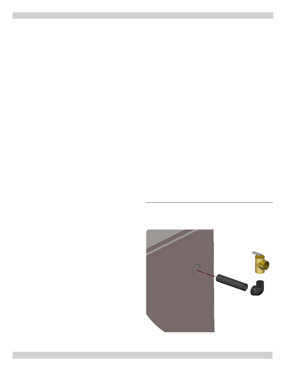
5.
Install Safety Relief valve in rear section using ¾”
nipple and street elbow provided with boiler. See figure
6.
A. Install safety relief valve with spindle in vertical
position.
B. Do not install shutoff valve between boiler and
safety relief valve.
C. Install discharge piping from safety relief valve.
• Use ¾” or larger pipe.
• Use pipe suitable for temperatures of 375°F
(191°C) or greater.
• Individual boiler discharge piping shall be
independent of other discharge piping.
• Size and arrange discharge piping to avoid
reducing safety relief valve relieving capacity
below minimum relief valve capacity stated on
rating plate.
• Run pipe as short and straight as possible to
location protecting user from scalding and properly
drain piping.
• Install union, if used, close to safety relief valve
outlet.
• Install elbow(s), if used, close to safety relief valve
outlet and downstream of union (if used).
• Terminate pipe with plain end (not threaded).
6.
Verify clean cold water supply is available when
connecting to pressure reducing valve. Use sand
strainer or pump strainer when water supply is from
well.
Low Design Water Temperature Systems (Below 140°
F) And Large Water Content Systems
Significant condensation may form in this boiler and/
or venting system if boiler is operated with return
temperatures of less than 120° F.
Condensation is corrosive and can eventually cause damage
to boiler and venting system. Minimum design return water
temperature to prevent this condensation in boiler and
venting is 120°F.
Boiler used in heating system where design water
temperatures below 140°F are desired (e.g. radiant floor
heating), a 3-way or 4-way mixing valve or suitable
alternative (e.g. Bypass Piping Arrangement shown
in diagram on following page) is required to prevent
low temperature (below return 120°F) return water
from entering boiler. When using mixing valve, follow
manufacturer’s installation instructions.
Boiler connected to system having large water content
(such as former gravity system), use of Bypass Piping
Arrangement shown in diagram on following page is
suggested.
SYSTEM PIPING
Follow instructions
to install discharge
piping from safety
relief valve to drain.
Figure 6 - Safety Relief Valve Installation