Water source heat pump module, Module overview, Technical guide 4 overview – Orion System Water Source Heat Pump Module User Manual
Page 4: Features, Figure 1: water source heat pump module, Distribution module to e-bus interface
Water Source Heat Pump Module
Technical Guide
4
Overview
The Water Source Heat Pump Module monitors the compressors on an
AAON
®
Water Source Heat Pump unit and can disable the compres-
sors based on low Suction Pressure, Leaving Water Temperature, and
Water Proof of Flow inputs. It also utilizes a Delay Timer to prevent the
compressors from turning on at the same time.
There is one water-only version of the Water Source Heat Pump Mod-
ule—the OE334-23-WPM-C which uses R-410A refrigerant.
There are also two 410-A glycol versions—the OE334-23-WPM-C20
which uses 20% glycol and the OE334-23-WPM-C40 which uses 40%
glycol.
The Water Source Heat Pump Module can be used stand-alone. It can
also be connected to the VCM-X WSHP Controller (OE332-23-VCMX-
WSHP-C) using the E-BUS Distribution Module (OE365-23-EBD-C).
This allows the Water Source Heat Pump Module to receive control data
and alarms from the VCM-X WSHP Controller.
The Water Source Heat Pump Module requires a 24 VAC power con-
nection with an appropriate VA rating.
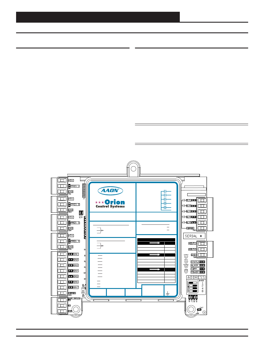
Module Overview
Figure 1: Water Source Heat Pump Module
Features
The Water Source Heat Pump Module provides the following:
Can be operated stand-alone or connected to a
VCM-X WSHP Controller using the E-BUS
Distribution Module to E-BUS interface
Capable of controlling digital compressors when
connected to the VCM-X WSHP Controller
Monitors suction pressure, leaving water
temperature, and water proof of fl ow
Provides Delay Timer to prevent compressors
from turning on at the same time
NOTE: The Water Source Heat Pump Module contains no user-
serviceable parts. Contact qualifi ed technical personnel
if your Module is not operating correctly.
WATTMASTER CONTROLS
Y 102374 REV 0
S
MADE IN USA
WattMaster Label
#LB102069-B
Rev.: 1E
E-BUS
Connector
E-BUS
Connector
+24
VAC
GND
WSHP Module
Orion No.: OE334-23-WPM-C
AAON Coil No.: 30318
www.aaon.com
www.orioncontrols.com
RELAY CONTACT RATING
IS 1 AMP MAX @ 24 VAC
COMP. A2 ENABLE
COMP. A1 ENABLE
R1
R2
R3
R4
R5
RC
RELAY COMMON
COMP. B1 ENABLE
COMP. B2 ENABLE
ALARM OUTPUT
+5V
PRES
GND
+5V
PRES
GND
BIN 1
BIN 2
BIN 3
BIN 4
BIN 5
BIN 6
BIN 7
COM
SUCT. PR. SENSOR
PRES 1=A1, PRES 2=N/A
PRES 3=B1, PRES 4=N/A
NOT USED
PRES 1=A1, PRES 2=N/A
PRES 3=B1, PRES 4=N/A
COMP. A1 ENABLE
COMP. A2 ENABLE
COMP. B1 ENABLE
COMP. B2 ENABLE
COOL ENABLE
WATER POF
NOT USED
COMMON
T 1
T 2
GND
LEAVING WATER TEMP
GROUND
NOT USED
LED BLINK CODES
LED NAME
STATUS
OFF MODE
1
COOLING MODE
2
HEATING MODE
3
LED NAME
ALARM
LOW SUCTION PRESSURE
1
COMPRESSOR LOCKOUT
2
WATER FLOW FAILURE
3
LOW LEAVING WATER TEMP.
4
LED NAME
PRES 1-4
SENSOR DETECTED
ON
NO SENSOR DETECTED
OFF
LOW SUCTION PRESSURE
1
COMPRESSOR LOCKOUT
2
AO1
A2O
CIRCUIT A -COMP. A1
+5 NOT USED, PRES TO P6 & GND TO P5
+5 TO RED, PRES TO WHT & GND TO BLK
CONNECT TO CNTLR C2 TERM.
CIRCUIT B - COMP. B1
DIGITAL COMRESSORS
DIGITAL COMP. A1 & B1
NON-DIGITAL COMPRESSORS