Wshp-x module, Installation & wiring, Technical guide 4 – Orion System Water Source Heat Pump X Module User Manual
Page 4: Power supply, Environmental requirements, Mounting
WSHP-X Module
Technical Guide
4
Installation & Wiring
Power Supply
The WSHP-X Module requires a 24 VAC power connection with an
appropriate VA rating.
If you will be connecting the WSHP-X Module to a VCM-X WSHP
Series Controller or SA Series Controller, one of the most important
checks to make before powering up the system for the fi rst time is to
make sure that the Controller is confi gured properly for your applica-
tion. Refer to the VCM-X Controller Technical Guide, VCM-X Modular
E-BUS Controller Technical Guide, SA Controller Technical Guide, or
SA E-BUS Controller Technical Guide for more information.
WARNING: Observe polarity! All boards must be wired
GND-to-GND and 24 VAC-to-VAC. Failure to
observe polarity could result in damage to the
boards.
Environmental Requirements
The WSHP-X Module needs to be installed in an environment that can
maintain a temperature range between -30°F and 150°F and not exceed
90% RH levels (non-condensing).
Mounting
The WSHP-X Module is housed in a plastic enclosure. It is designed to
be mounted by using the 3 mounting holes in the enclosure base. It is
important to mount the module in a location that is free from extreme
high or low temperatures, moisture, dust, and dirt. Be careful not to
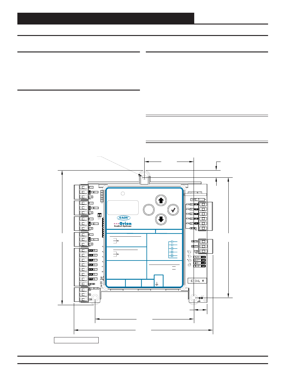
damage the electronic components when mounting the module. See
Figure 2 for Module dimensions (in inches).
Figure 2: Water Source Heat Pump X Module Dimensions
WATTMASTER CONTROLS
5.64
5.83
2.07
4.14
5.05
0.29
0.56
0.18 DIA. TYP. 3 PL.
Note: Height is 1.49 inches.
M
ENTER
UP
DOWN
ALARM
MENU
OE334-26-WSHPX-A WSHP-X MODULE
AAON NO.: V18330
WattMaster Label
#SW000054
Rev.: 1A
E-BUS
CONNECT
E-BUS
CONNECT
+24
V
AC
GND
www.orioncontrols.com
www.aaon.com
BIN 1
BIN 2
BIN 3
BIN 4
BIN 5
BIN 6
BIN 7
COM
- COMP. A1 EN.
- HEAT ENABLE
- COMP. A2 EN.
- WATER POF
- COMP. B1 EN.
- WATER POF
- COMP. B2 EN.
- COMMON
T 1
T 2
GND
- LEAVING WATER TEMP A
- GROUND
- LEAVING WATER TEMP B
AO1
A2O
STAGE 1- COMP. A1/B1-
STAGE 2 - COMP. A2/B2
DIGITAL COMP. A1, A2, B1, B2
RELAY CONTACT RATING
IS 1 AMP MAX @ 24 VAC
COMP. A2 ENABLE
COMP. A1 ENABLE
R1
R2
R3
R4
R5
RC
RELAY COMMON
COMP. B1 ENABLE
COMP. B2 ENABLE
ALARM OUTPUT
CONNECT TO CNTLR C2 TERM.
+5V
PRES
GND
+5V
PRES
GND
SUCT. PR. SENSOR
PRES 1=A1, PRES 2=A2
PRES 3=B1, PRES 4=B2
NOT USED
PRES 1=A1, PRES 2=A2
PRES 3=B1, PRES 4=B2
+5 NOT USED, PRES TO P6 & GND TO P5
+5 TO RED, PRES TO WHT & GND TO BLK
DIGITAL COMRESSORS
NON-DIGITAL COMPRESSORS