Wiring, Modgas-x field technical guide – Orion System MODGAS-X User Manual
Page 9
MODGAS-X Field Technical Guide
WIRING
9
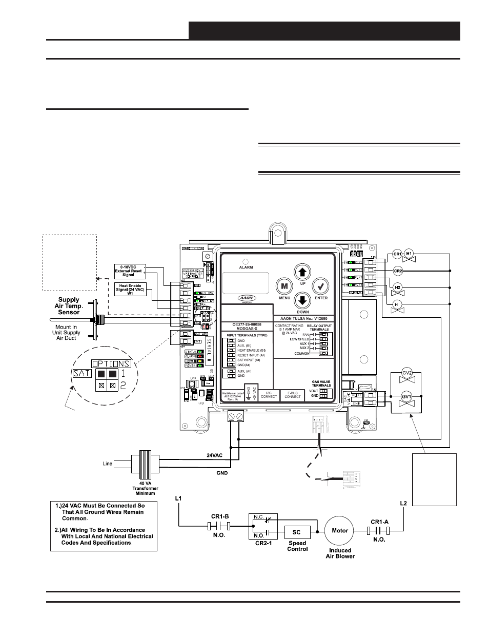
Two Modulating Valves & Up To 13 Stages Fixed Heat Stand-Alone
Figure 6: Two Modulating Valves - Stand-Alone
MODGAS-X CONTROLLER
(OE377-26-00058)
See
For
Settings.
Only One Supply Air Temperature Sensor
Can Be Used Per Application.
Table 8, Page 24
SAT OPTIONS Jumper
EBC-E-BUS Cable
Connects To
12 Relay E-BUS
Expansion
Port
Fan Enable And
Stage 1 Heat (Mod)
Low Speed Fan
Stage 2 Heat (Mod)
Stage 3 Heat (Fixed)
3
Connect SAT and
Input to
Board’s
Input If
Applicable.
See
.
GND
Reheat
SAT
Table 7,
Page 24
24 VAC Power
Input Terminals
Max. Power
Consumption
1 Gas Valve
= 18 VA
2 Gas Valves
= 33 VA
Two Modulating Valves With Up To 13
Additional Stages Of Fixed Heat
Stand-Alone Wiring
This confi guration only applies to a Stand-Alone operation (Figure
6, below) and is factory-confi gured.
In this confi guration, the fi rst Modulating Valve is enabled by the
FAN RLY. The second Modulating Valve is enabled by the AUX1
relay. The fi xed stage uses the AUX2 relay to enable it (Figure 6,
below). Additional fi xed stages can be added by using the 12-Relay
E-BUS Expansion Module. (Figure 7, page 10).
If using a MHGRV-X Controller along with the MODGAS-X
Controller in Stand-Alone, the SAT Sensor always connects to the
MODGAS-X Controller.
This configuration
can use either the MAXITROL
®
0-20 volt
valve(s) or the MAXITROL
®
EXA STAR 0-10 volt stepper valve(s)
(confi gured at the factory).
See Appendix C, page 26 for depiction.
WARNING: Do Not Connect Power To VOUT/Ground
Terminal
Block!
Revised 9/30/14