Appendix c - reheat expansion module, Wiring, Mhgrv-x field technical guide 22 – Orion System MHGRV-X User Manual
Page 22: Reheat expansion module(s) wiring, Figure 9: reheat expansion module(s) wiring
APPENDIX C - REHEAT EXPANSION MODULE
MHGRV-X Field Technical Guide
22
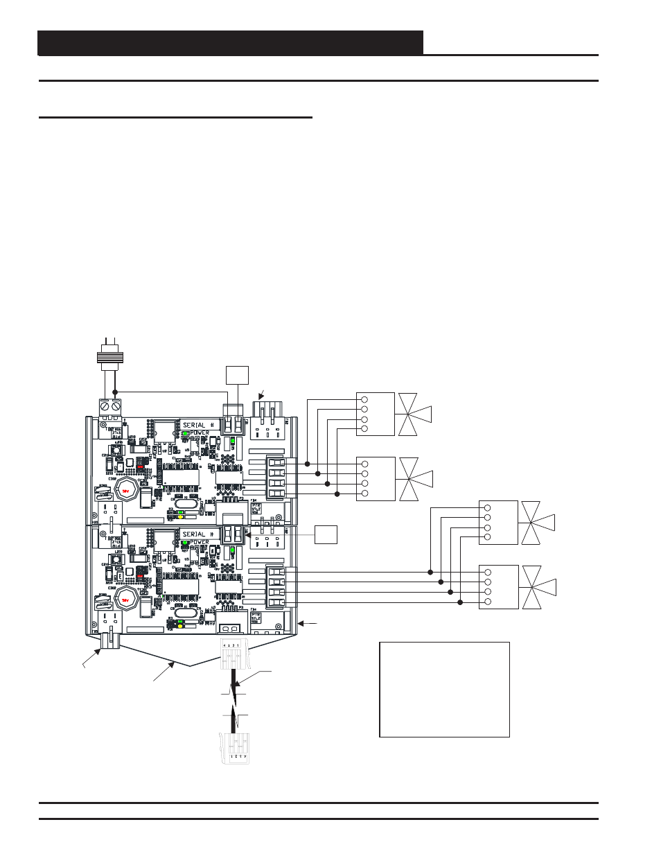
Figure 9: Reheat Expansion Module(s) Wiring
Wiring
24
V
A
C
GN
D
CO
M
M
GN
D
EN
AB
L
E
BLACK
WHITE
RED/GRN
GRN/RED
COND/REHEAT
YS102608 R0
WATTMASTER
CONTROLS INC
2013
COMM
STATUS
24
V
A
C
GN
D
CO
M
M
GN
D
EN
AB
L
E
BLACK
WHITE
RED/GRN
GRN/RED
COND/REHEAT
YS102608 R0
WATTMASTER
CONTROLS INC
2013
COMM
STATUS
Last Reheat
Expansion Module
In A Series
Connects To
MHGRV-X
Controller
Power
Connector
Comm
Connector
Chevron Cut
Snap Track
Line
GND
24VAC
12 VA
Transformer
Minimum
RED
GRN
WHT
BLK
Condenser Valve #1
HGR Valve #1
RED
GRN
WHT
BLK
NOTE:
1.) Connect The Next Reheat
Expansion Module To The
Power Connector And Comm
Connector Of The Previous
Reheat Expansion Module In
A Series. Up to (7) Expansion
Modules Can Be Connected.
Compressor #2
Enable Relay
C2
Comm
Connector
OE377-01-00059
Reheat Expansion Module
(2)
Shown Connected Together
Up to (7) Expansion Modules Can Be Connected
RED
GRN
WHT
BLK
Condenser Valve #2
HGR Valve #2
RED
GRN
WHT
BLK
EBC E-BUS
Cable
Compressor #3
Enable Relay
C3
Reheat Expansion Module(s) Wiring
Reheat Expansion Modules snap into each other at the power and
Comm connectors. Up to (7) Reheat Expansion Modules can be used.
Apply power to the fi rst Reheat Expansion Module in a series. The
last Reheat Expansion Module in a series connects to the MHGRV-X
Controller using an EBC E-BUS cable.
See Figure 9 below for details.