Gbd-x wiring – Orion System GBD-X Controller User Manual
Page 10
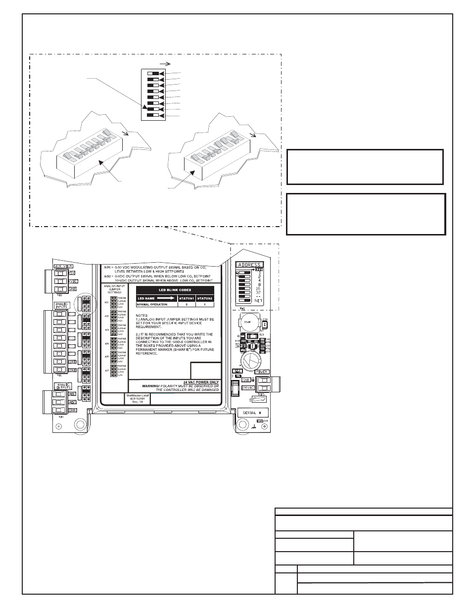
16
32
- -
NET
8
4
2
1
Address Switch Shown Is
Set For Address 1
Address Switch Shown Is
Set For Address 13
Controller
Address Switch
This Switch Should Be
In The OFF Position
As Shown
Note:
The Power To The Controller Must Be Removed And
Reconnected After Changing The Address Switch
Settings In Order For Any Changes To Take Effect.
Caution
Disconnect All Communication Loop Wiring From The
Controller Before Removing Power From The Controller.
Reconnect Power And Then Reconnect Communication
Loop Wiring.
ADDRESS
ADD
ADDRESS
ADD
ADDRESS
ADD
The Address For Each Controller
Must Be Unique To The Other Controllers
On The Local Loop And Be Between 1 and 60
FILENAME
DATE:
B. CREWS
DESCRIPTION:
PAGE
DRAWN BY:
OE332-23- GBDX Controller
JOB NAME
OE332-23-GBDX-Wire1A.CDR
FILENAME
JOB NAME
5 of 5
GBD-X Wiring
4.) All Wiring To Be In Accordance
With Local And National Electrical
Codes And Specifications.
3.) Set-up, Programming And
Monitoring Of The GBD-X
Controller Requires The Use Of A
Personal Computer And Prism
Software.
2.) 24 VAC Must Be Connected
So That All Ground Wires
Remain Common.
Notes:
1.) The GBD-X Can Either Be Used
With CO2 Sensors Or Space
Temperature Sensors But Not
Both On The Same GBD-X
Controller. Up to 2 GBD
Controllers Can Be Located On
Each Local Loop.
AI1
AI1
SET
AI2
SET
AI3
SET
AI4
SET
AI5
SET
AI7
SET
AI2
AI3
AI4
AI5
AI7
OE331-21-AVG
GBD Device Wiring
Address Switch Setting Information
10/21/10