Troubleshooting – Orion System E-BUS Distribution User Manual
Page 9
Technical Guide
E-BUS Distribution Module
9
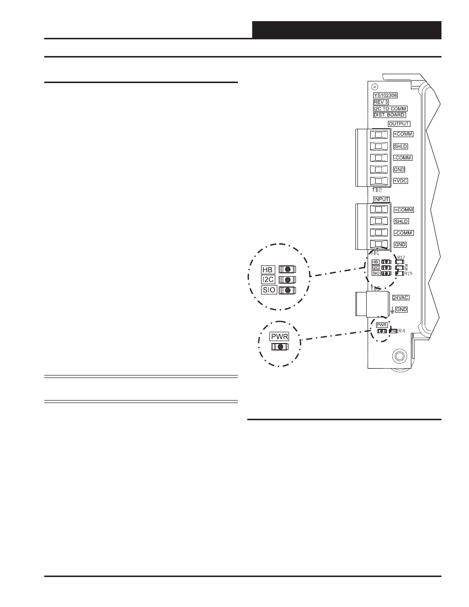
Using LEDs to Verify Operation
The E-BUS Distribution Module is equipped with LEDs that can be
used to verify operation and perform troubleshooting. The module has
four LEDs—one used for power and the others for communication. See
Figure 7 for the LED locations. The LEDs associated with these inputs
and outputs allow you to see what is active without using a voltmeter.
The LEDs and their uses are as follows:
Status LEDs
“PWR” - This LED will light up to indicate that 24 VAC power has
been applied to the controller.
“HB” - If the board is programmed and the program is running, this
LED will blink rapidly like a heartbeat. If the LED is not blinking, the
board is either not powered up or is dead.
Communication LEDs
“SIO” - After the E-BUS Distribution Module receives a valid request
for information, it will send it out on the E-BUS side. At this time, this
LED will blink. If this LED is not blinking, check the connections on
the E-BUS side.
NOTE: In normal operation, the I
2
C and SIO LEDs should be
alternating back and forth.
Figure 7: LED Locations
Troubleshooting
“I2C” - When the VCM-X Controller, VCM-X Modular Controller,
VCM-X WSHP Controller, VCM-X Expansion Module, SA Controller,
SA Expansion Module, or 12 Relay Expansion Module sends a request
for information via the I
2
C Port, this LED will blink on stating that the
board received the request. If this LED is not blinking from time to time,
Check the I
2
C cable connections.