E-bus adapter board, Technical guide, Connecting to the vcm-x e-bus or rne controller – Orion System OE365-15-EBA User Manual
Page 5: Figure 3: ebtron, Gtc116 series and greentrol, Gtc116 series* or greentrol, Or greentrol
Technical Guide
E-BUS Adapter Board
5
Airfl ow Monitoring Station to VCM-X E-BUS or RNE Controller Wiring
Connecting to the VCM-X E-BUS or
RNE Controller
NOTE: Only the EBTRON
®
GTC116 series* or GreenTrol
TM
GA-200-N Module (with GF series Airfl ow Station)
of MODBUS transmitters are compatible with the
VCM-X E-BUS or RNE Controller.** No other series of
EBTRON
®
or GreenTrol
TM
transmitters will work for
this application.
The E-BUS Adapter Board attaches to the VCM-X E-BUS or RNE
Controller with an HSSC E-BUS cable (supplied separately). The
Adapter Board is used for connecting the EBTRON
®
or GreenTrol
TM
Airfl ow Measurement Digital Transmitter to the VCM-X E-BUS
or RNE Controller. You must wire the EBTRON
®
or GreenTrol
TM
Airfl ow Measurement Digital Transmitter to the Adapter Board as
shown in Figure 3.
NOTE: Up to 3 EBTRON
®
or GreenTrol
TM
Airfl ow
Measurement Digital Transmitters can be
attached to each Adapter Board.
*NOTE: When confi guring the GTC-116 Series, be sure to
set the Parity to “NO PARITY, 1 STOP BIT.”
**NOTE: With custom VCM-X / RNE software, Paragon Micro-
Trans
EQ
Airfl ow Stations can be used and would wire
into the E-BUS Adapter Board the same way. The
Paragon MODBUS ID must be set to 9 and the baud
rate must be set to 9600.
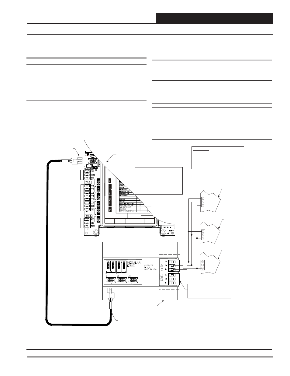
Figure 3: EBTRON
®
GTC116 Series and GreenTrol
TM
GA-200-N Series to VCM-X E-BUS or RNE Controller
Wiring (VCM-X E-BUS Controller Shown)
COMM
COMM
NET-
NET-
NET+
NET+
Airflow Measurement
Digital Transmitter Terminals
For Outdoor Air CFM
(Set Address Switch To 9)
Airflow Measurement
Digital Transmitter Terminals
For Return or Exhaust Air CFM
(Set Address Switch To 10)
Airflow Measurement
Digital Transmitter Terminals
For Supply Air CFM
(Set Address Switch To 11)
COMM
NET-
NET+
OE332-23E-VCMX-MOD
VCM-X E-BUS Controller
OE365-15-EBA
E-BUS Adapter Board
I2C DIGITAL
SENSOR
I2C
EXPANSION
STATIC
PRESSURE
ANALOG INPUT JUMPER SETTINGS
MUST BE SET AS SHOWN FOR
PROPER OPERATION
24 VAC POWER ONLY
WARNING! POLARITY MUST BE OBSERVED
OR THE CONTROLLER WILL BE DAMAGED
AI2
AI3
AI4
THERM
THERM
THERM
THERM
4-20mA
4-20mA
4-20mA
4-20mA
4-20mA
0-10V
0-10V
0-10V
0-10V
0-10V
0-5V
0-5V
0-5V
0-5V
0-5V
AI5
AI7
WattMaster Label
#LB102033-01
AI1 AI2 SET
AI3 SET
AI4 SET
AI5 SET
AI7 SET
AI2
AI3
AI4
AI5
AI7
EMERGENCY SHUTDOWN
AI1 SET
AI1
THERM
THERM
4-20mA
0-10V
0-5V
ANALOG INPU
JUMPER
SETTINGS
HSSC Cable Connect To
HSSC E-BUS Port
Connect To
VCM-X or RNE E-BUS Port
WARNING!!
Observe Polarity! All boards
must be wired with GND-to-GND
and 24 VAC-to-24 VAC. Failure
To observe polarity could result in
damage to the boards.
Size Transformer For
Correct Total Load.
VCM-X E-BUS or RNE
Controller = 8 VA.
Power Terminal Block Not
Shown.
NOTE:
NOTE: One Or Both
Terminal Blocks Can be
Used.