Installation, Continued – Desa FPVF33NRA User Manual
Page 12
www.desatech.com
113109-01D
1
INSTALLATION
Continued
2. If using blower, install and properly ground
GA3555, three-prong 120 volt electrical
outlet, in fireplace. Follow instructions in-
cluded in kit (see Accessories, page 38).
3. Install gas piping to fireplace location. This
installation includes an approved flexible
gas line (if allowed by local codes) after the
equipment shutoff valve. The flexible gas
line must be the last item installed on the gas
piping. See Installing Gas Piping to Fireplace
Location, page 13.
4. Carefully set fireplace in front of rough
opening with back of fireplace inside wall
opening.
5. Plug electrical cord into electrical outlet
installed in step .
6. Carefully insert fireplace into rough
opening.
7. Attach flexible gas line to gas supply.
See Connecting Fireplace to Gas Supply,
page 14.
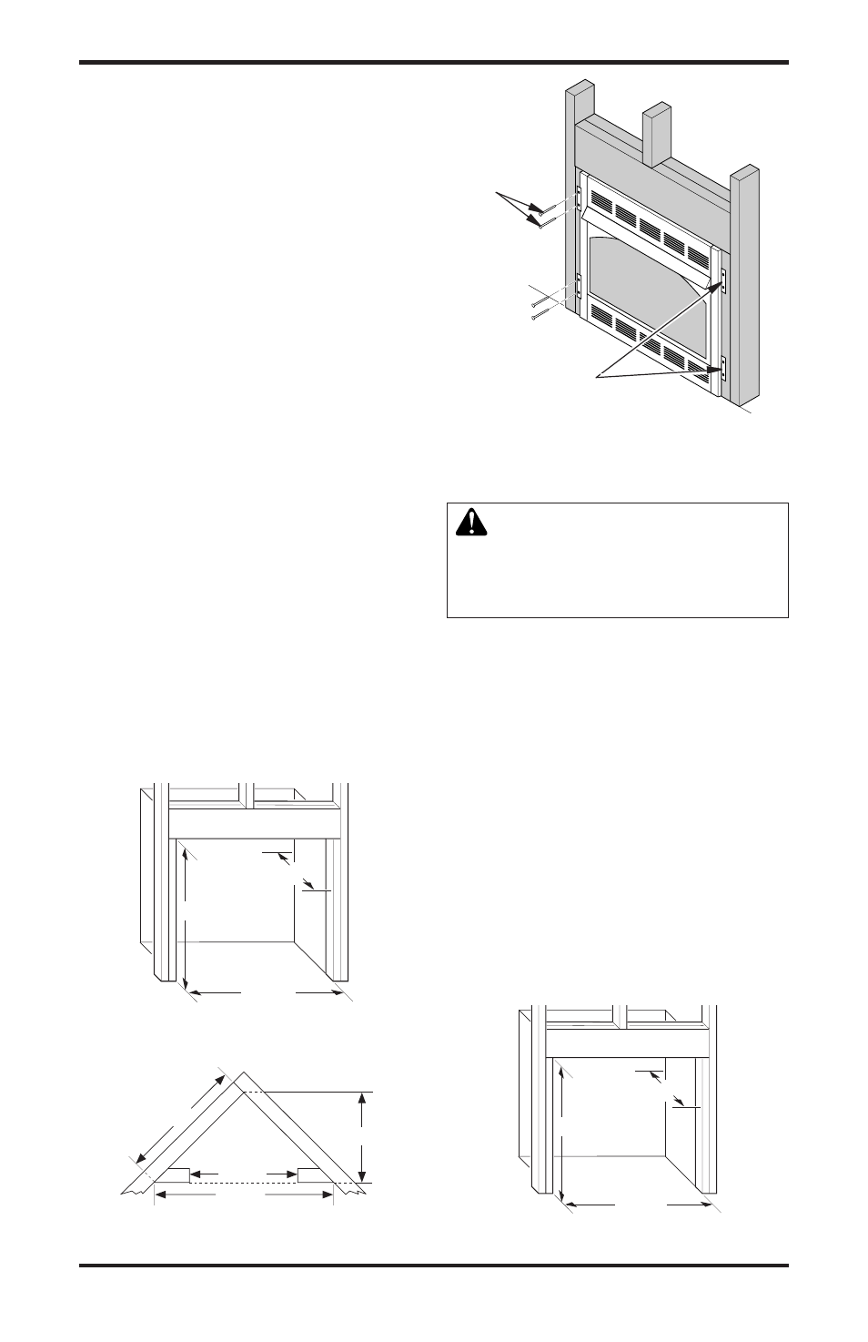
8. Attach fireplace to wall studs using nails
or wood screws through holes in nailing
flange (see Figure 15).
9. Check all gas connections for leaks. See
Checking Gas Connections, page 15.
10. Install perimeter trim after final finishing
and/or painting of wall (see Figure 7,
page 9).
35
1
/
2
"
17
3
/
4
"
33"
Figure 16 - Rough Opening for Installing
in Wall
35
1
/
2
"
17
3
/
4
"
33"
Figure 13 - Rough Opening for Installing
in Wall
39
3
/
8
"
27
7
/
8
"
55
5
/
8
"
35
1
/
2
"
Figure 14 - Rough Opening for Installing
in Corner
Figure 15 - Attaching Fireplace to Wall
Studs
Nailing
Flanges
Nails or
Wood
Screws
Models FPVF33PRA and FPVF33NRA
WARNING: A qualified electri-
cian must connect electrical wiring
to duplex outlet for built-in instal-
lation. Follow all local codes.
1. Frame in rough opening. Use dimensions
shown in Figure 16 for the rough opening.
2. If using blower, install wiring and properly
ground the three-prong, 120 volt electrical
outlet in fireplace.
3. Before replacing bottom of firebox, install
duplex outlet to the right support bracket
in the bottom of firebox (see Figure 17,
page 13).
4. Route wires from electrical box through
smallest hole in outer casing using strain
relief fitting provided (see Figure 17,
page 13).
5. Connect wires from the electrical box to
duplex outlet. Match wire colors to those
indicated on duplex outlet. Be sure to
connect ground wire.