Ò³ãæ 25, Autopilot installation, 1 installation of main unit – Onwa Marine Electronics KAP-866 User Manual
Page 25: 1 position, 2 wiring, 3 magnetic effect, 4 power supply consideration
3. AUTOPILOT INSTALLATION
3. AUTOPILOT INSTALLATION
-
+
3.1 Installation of Main Unit
3.1.1 Position
The KAP-866 main panel should be mounted in an accessible position, Protec-
ted from rain or salt water.
3.1.2 Wiring
Cablings have to be run from KAP-866 to the rudder feedback unit, compass
unit, compass unit and steering drive system. Wiring should be kept as far away
as possible from radio aerials and aerial cables to prevent interference to the
radio, and to prevent transmitted signals from the radio influencing to the
autopilot. The power source for the autopilot should be fused separately from
other equipment. Maintain conventional colour coding and, if necessary, mark
the cables for ease of identification.
Connection - As per diagram labelled Connection Diagram for KAP-866.
3.1.3 Magnetic Effect
As a minimum amount of steel is used in the control unit. there is negligible
effect on a steering compass. Some radio interference may be caused and the
routing of cables should be considered when wiring the vessel.
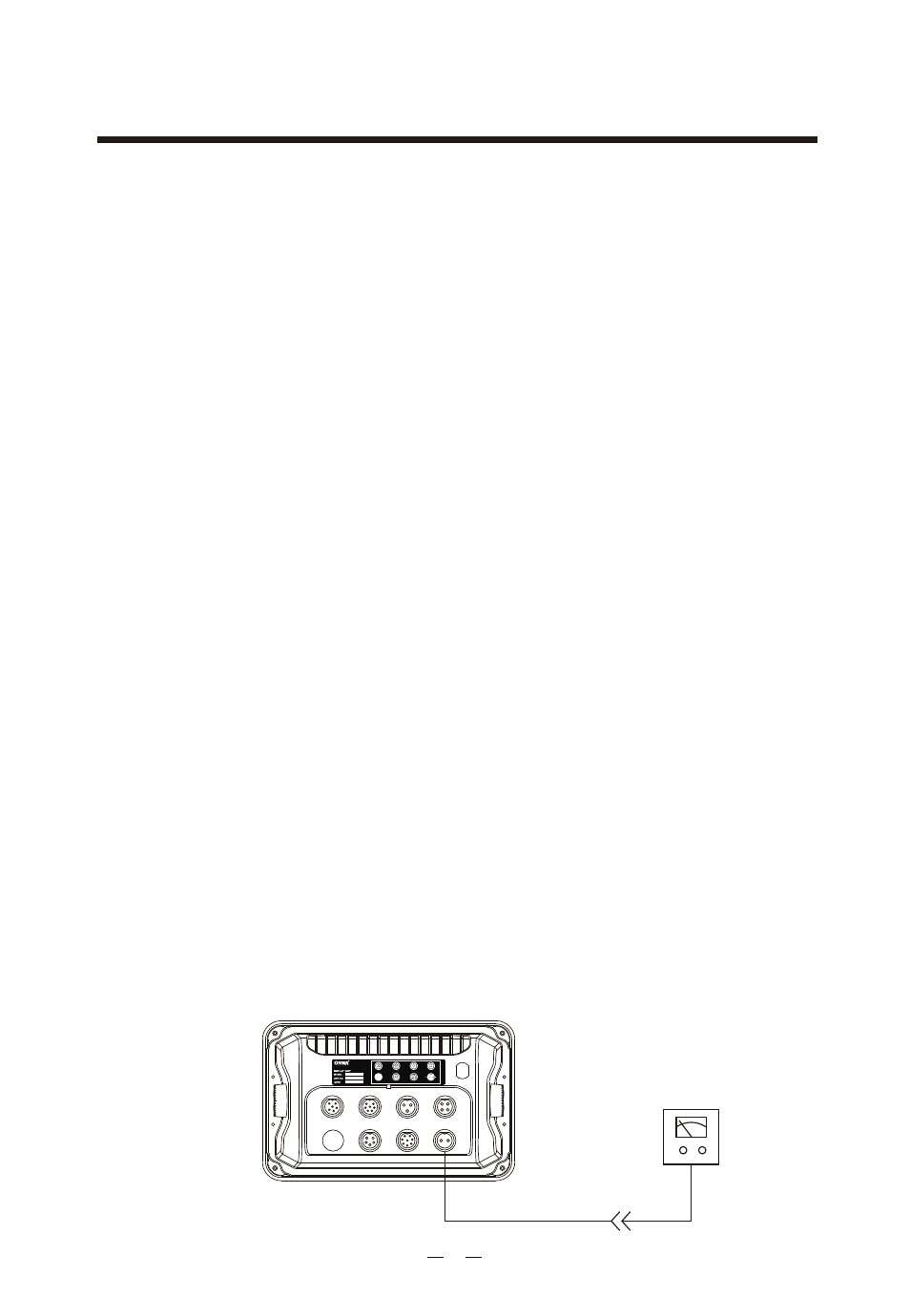
3.1.4 Power supply consideration
KAP-866 can be operated with 12VDC or 24VDC. To consider to use 12VDC
or 24VDC you have to find out the operating voltage of steering drive system
onboard first. Usually the steering drive system is solenoid drive or reversing
motor drive. If the steering drive system onboard is operated on 12VDC the
you have to connect 12VDC power suppl to KAP-866. If the steering drive
system onboard is operated on 24VDC then you have to connect 24VDC power
supply to KAP-866.
POWER SUPPLY
12VDC or 24VDC
20
AUTOPILOT
COMPASS
REMOTE
RUDDER
MOTOR
ALA/RUDM
NMEA I/O
POWER IN