Online power – OnLine Power Constant Power 3 User Manual
Page 27
OnLine Power
6002-034 REV. C
3-6
3-4-9
Constant Power 6 with 208-220-240 Volt Input (continued)
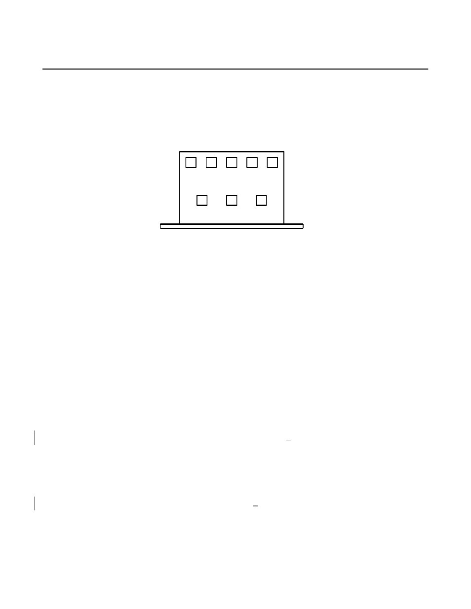
MOUNTING PANEL
1
2
3
8
6
10
4
5
COMMON 120
208
220
240
200 VAC INPUT REFERENCE TRANSFORMER
ILLUSTRATION 3-1
There will be 2 wires, 1 lug, on the common terminal. There will be 1 wire, 120VAC, on terminal 2. This powers
the Power On lamp. Terminals 3, 4 and 5 select the 208, 220 and 240 VAC input. Select the terminal that
matches the lug selected on the main transformer input. Remember the Constant Power 6 reference transformer
tap selection must match the main transformer tap selected. If this is not done, incorrect output voltages can
result from the Constant Power 6 and cause damage to the load being powered by Constant Power 6.
3-4-10 Start-up for the Constant Power 6, Constant Power 3, and Mini-Power
1.
Constant Power 6 Start-Up. Verify the input voltage to the Constant Power 6 is matches the nameplate
located on the bottom center of the rear panel. Remember the input voltage can be nominal to plus 10% or
minus 26%. Connect the input power cable and make sure the output circuit breakers are OFF on original
start-up. Place the bypass switch in the AUTO position. Turn on the Input Power circuit breaker and note
the Power On lamp turns on at the same time. After 6 seconds, one lamp only will turn on of the 6 operating
range indicators. Turn on one of the output circuit breakers and check the corresponding socket for the
correct output voltage. Remember the output voltage is identified on the label plate located on the bottom
center of the rear panel. The output voltage must be rated voltage
+
4%.
2.
Constant Power 3 and Mini-Power Start-Up. Check the input power at the source and be sure this matches
the nameplate on the rear panel of the Constant Power 3. Remember the input range is nominal plus 7% to
minus 23%. Plug the input cable to the socket with the input power circuit breaker in the OFF position.
Place the bypass switch in the AUTO position. Disconnect output loads from the output sockets. Turn on
the Input Power breaker and the Power On lamp will turn on. After 6 seconds, the output power will turn on.
Measure the output power. It must match the nameplate
+
5%.
3-2
CONFIGURATION
The unit is shipped factory configured. No configuration is necessary. Do not change tap connections.