Output – Norsat 100W ATOM User Manual
Page 20
ATOM 100W
Revision 1.1
908236
20
908236_r1.1 - Operator Manual ATOM KU
100W.doc
AC Unit J3 Connector Pin Outs
18-12
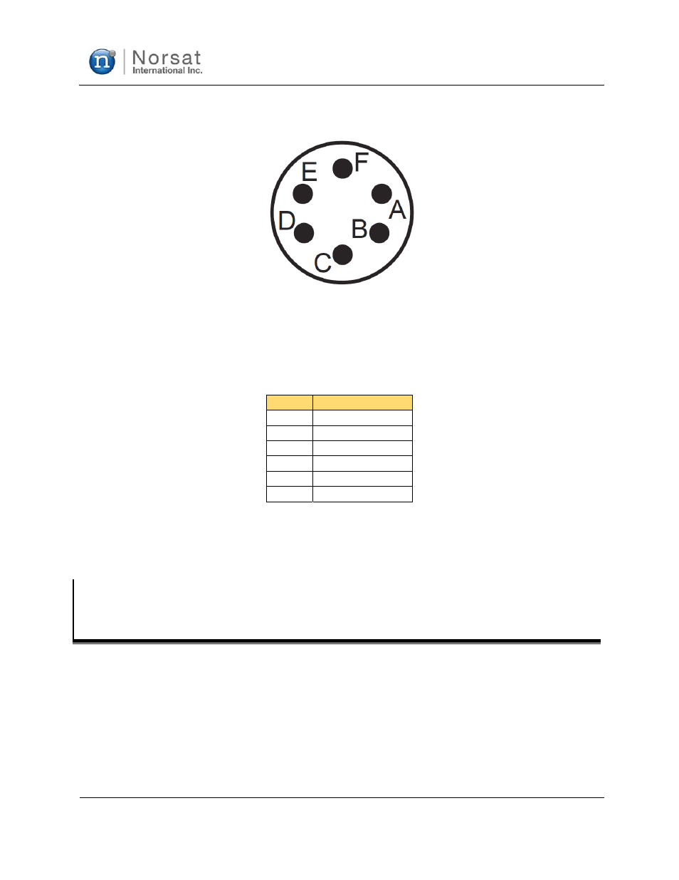
Figure 2-5: AC Unit J3 Connector Pin Out, Viewed Looking at Unit from the Outside
Table 2-5: AC Unit J3 Connector Pin Out
Pin
Name
A
208V AC Phase 1
B
208V AC Phase 2
C
208V AC Phase 3
D Ground
E No
Connection
F No
Connection
For the 208V AC 3-phase input, one phase is applied to pin A, another phase is applied to pin B, and the
last phase applied to pins C. Earth ground should be connected to pin D, which is internally connected to
the case ground internally.
Section 2.5
J4
–
RF
OUTPUT
The output is a standard WR75 or WR62 square waveguide flange; customer to specify at time of order.
The unit is supplied with two screw lengths (four 6-32x3/8" and four 6-32x7/16"); it is the users
responsibility to ensure that the appropriate length of screw is used. There should be at least 4 threads of
engagement (0.125") with the holes in the waveguide flange.