Onitor and, Ontrol, Nterface – Norsat 100W ATOM User Manual
Page 11
ATOM 100W
Revision 1.1
908236
11
908236_r1.1 - Operator Manual ATOM KU
100W.doc
Section 2.3
J2
–
M
ONITOR AND
C
ONTROL
I
NTERFACE
The serial interface is used to interface the unit to a host computer. All on-board sensors are read
through this interface, including forward power monitoring. Use of this connection is optional.
M
ONITOR AND
C
ONTROL
I
NTERFACE
P
IN
O
UTS
The monitor and control interface is a ten pin connector. It is a cannon type connector with a 12-10
configuration with pins (Amphenol part number 71-570123-10P). This connector is a MIL-C-26482 Series
1 receptacle, Shell size 12, 10 pins. The connector is a “receptacle” with pins (as opposed to sockets),
and requires the mating connector to be a “plug” with 10 sockets. An example mating connector would be
Amphenol #PT06A-12-10S. A range of plug-compatible Amphenol part numbers for the mating connector
may be used to add options to the plug such as right-angle, stress relief clamp, metal color/finish, etc.
Please contact the connector manufacturer for more information and/or see Amphenol catalog 12-070.
The pin outs are given in
Table 2-1
.
The GND pins are internally connected to the case ground. They also provide a ground reference for the
RS-485 address signal. If the RS-485 addressing function is used, one of the GND pins should be
connected to the RS-485 ground. If the RS-485 function is not used, these pins can be left floating, or it
can be externally connected to the case ground, if desired.
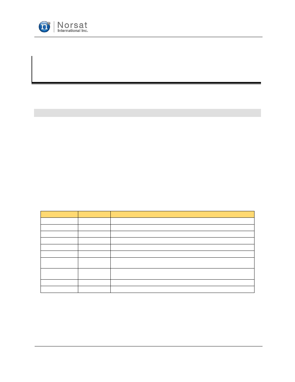
Table 2-1: J2 Pin Outs
Connector Pin
Function
Description
A
TX-
Host computer TX- signal (signal into unit)
B
TX+
Host computer TX+ signal (signal into unit)
C
RX+
Host computer RX+ signal (signal out of unit)
D
SHUTDOWN
Controls Muting of Amplifier
E
RS485_ADDR0
RS-485 Address 0
F
RS485_ADDR1
RS-485 Address 1
G
GND
Ground reference for RS-485 signals. This is internally connected to case
ground.
H
GND
Ground reference for RS-485 signals. This is internally connected to case
ground.
J
RX-
Host computer RX- signal (signal out of unit)
K
RS485_ADDR2
RS-485 Address 2