3 rear view – Nevion FR202 User Manual
Page 7
FR-2RU-20-2
Rev. A
nevion.com | 7
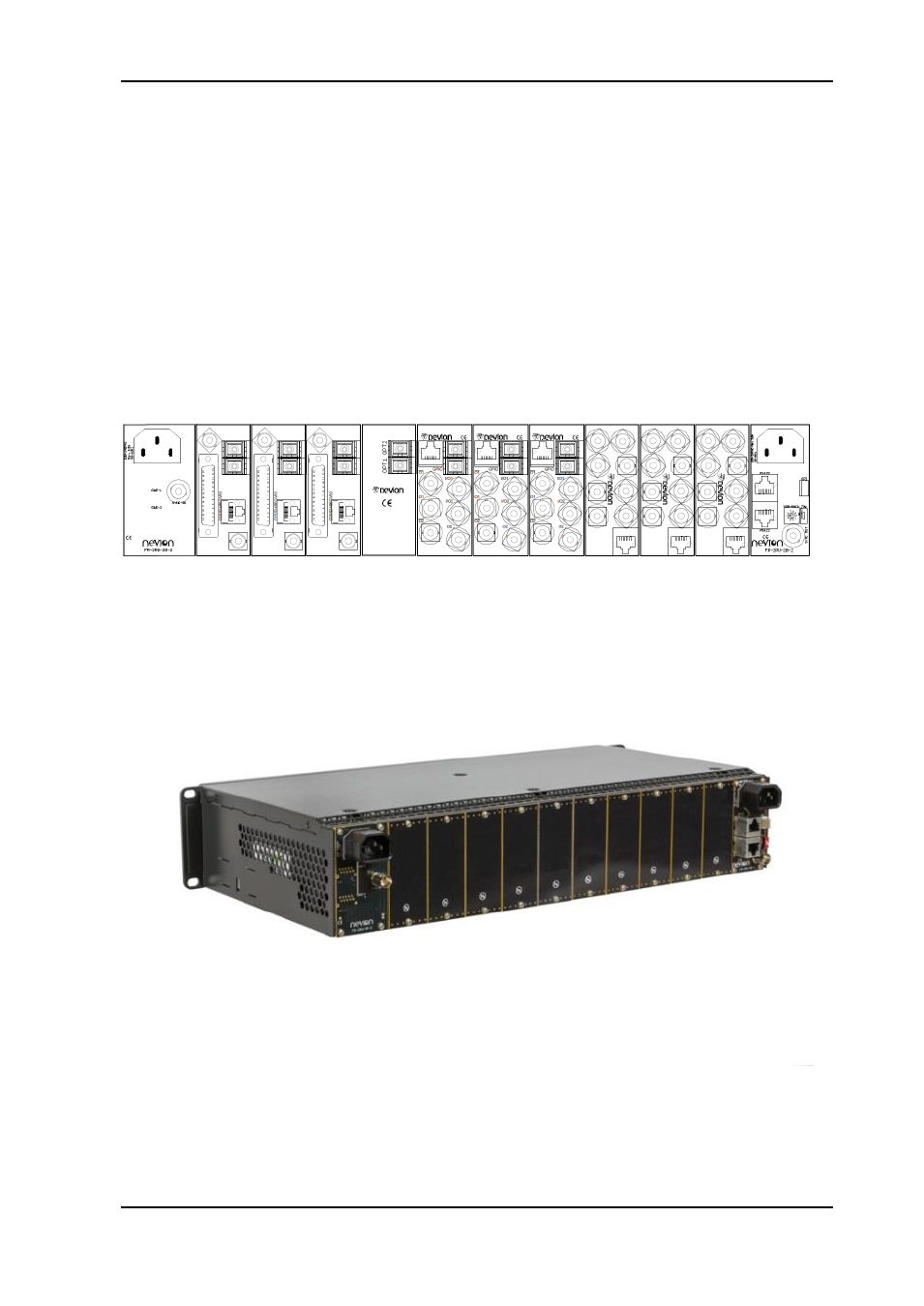
2.3 Rear view
Figure 2 shows an example of a fully equipped Flashlink frame, seen from the rear side.
The outer left and outer right modules are backplanes for the power supplies and contain
connections as follows;
-
Left backplane;
o IEC-C14 AC mains inlet
o BNC, sync in
-
Right backplane;
o IEC-C14 AC mains inlet
o BNC, sync out
o 2pcs. RJ-45 for RS-422 in/out
o Rotary switch for programming frame number to be read by Multicon
o 4 pin connector, GPI out
*The other connector modules are described in their respective user manuals.
Figure 2: Illustration of fully equipped Flashlink frame.
Figure 3: Flashlink frame equipped with blanks.
See also other documents in the category Nevion Optics:
- N-BOX (14 pages)
- FR-2RU-10-2 (28 pages)
- Flashcase-II model 1 (15 pages)
- FC-PWR (8 pages)
- SFP-TR10-13T-ER (9 pages)
- XFP-TR10-13T-ER (8 pages)
- SFP-TR1-D15xx.xx-ER (9 pages)
- SFP-TR10-D15xx.xx-ER (9 pages)
- SFP-TR1-13T-ER (8 pages)
- SFP-3G-RX-2-HDBNC (8 pages)
- SFP-3G-TX-2-DIN (8 pages)
- SFP-3G-OE-2 (8 pages)
- SFP-3G-EO-2-C1xxx (9 pages)
- SFP-3G-EO-OE-C1xxx-L (8 pages)
- WOS-2 (18 pages)
- EDFA-B-C 17dBm (17 pages)
- DWDM-40C (14 pages)
- DWDM-8C (12 pages)
- CWDM-18 (12 pages)
- CWDM 9-16-Mkll (15 pages)
- WDM-2-MkII (15 pages)
- WOC-4-25-Mkll (15 pages)
- 3GHD-EO-D15xx (18 pages)
- 3GHD-EO-2 (23 pages)
- 3GHD-EO-2-SFP (19 pages)
- FC-3G-EO-OE-28 (27 pages)
- 3GHD-OE-2-SFP (20 pages)
- LB-OE Rev.E (15 pages)
- LB-EO Rev.F (16 pages)
- Flashlink Compact II (29 pages)
- ETH-1000-SW-10G (15 pages)
- ETH1000-SW-COM (23 pages)
- ETH1000-SFP (15 pages)
- D422-MG (20 pages)
- 10G-TR-C1xxx (12 pages)
- HD-TD-10GX-8-SFP (21 pages)
- HD-TD-10GDX-6 (19 pages)
- SDI-TD-3GDX-5 (4 pages)
- HD-TD-3GDX-2 (38 pages)
- SDI-TD-DMUX-4 (30 pages)
- AES-VMUX/-SFP (37 pages)
- DWC-HD-R (33 pages)
- ARC-SD-DMUX-R (36 pages)
- ARC-SD-XMUX4 (35 pages)