Chapter 2 interfacing, Electrical power, Chapter 2 – NavCom SF-2040 Rev.F User Manual
Page 29: Interfacing, Table 2: external power cable pin-out
SF-2040 User Guide – Rev. F
Chapter 2 ................................. Interfacing
This chapter details the SF-2040 GPS sensor
connectors, LED display, appropriate sources of
electrical power, and how to interface the
communication ports.
Electrical Power
A 4-pin LEMO female connector provides electrical
power to the SF-2040. It is located below the indicator
panel labeled DC PWR. Pin assignments are given in
Table 2; see Figure 2 for pin location on the
connector.
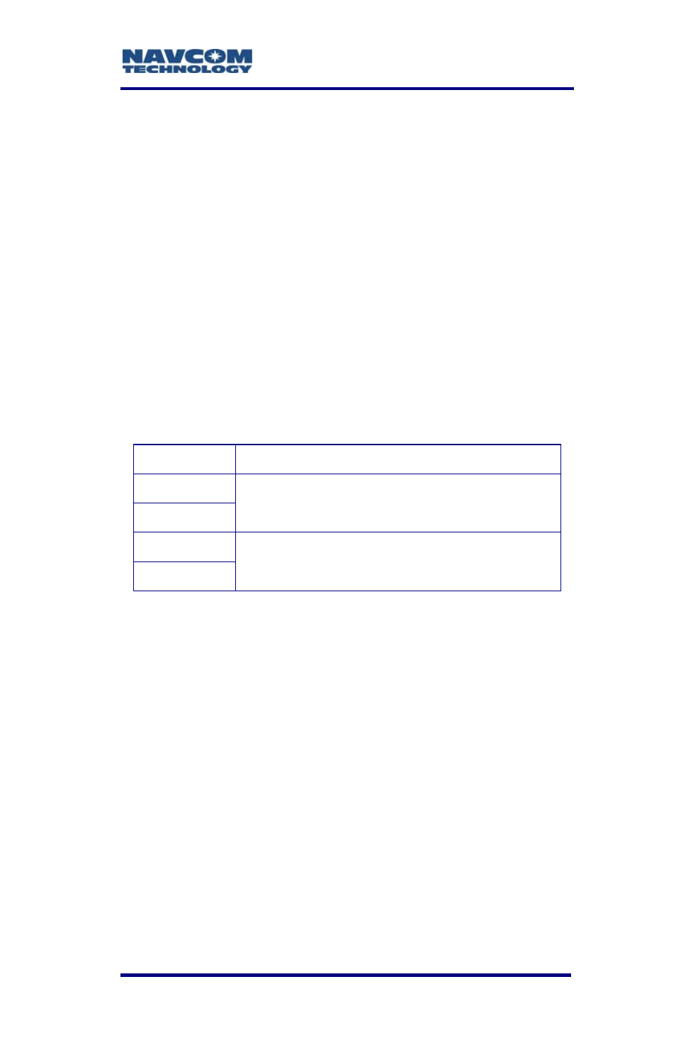
Table 2: External Power Cable Pin-Out
Pin Description
1
2
Return
3
4
Power Input 10 to 30 VDC; 8W
Pins 1 and 2 connect to the same internal point in the
SF-2040. Likewise, pins 3 and 4 connect to the same
internal point.
Power cable longer than 5m (15ft) must make
full use of all four power pins.
P/N 82-020002-5001 is an optional universal AC/DC
12V, 2A power adapter.
P/N 94-310060-3010 is an optional 10ft (3m)
unterminated power cable fitted with a LEMO plug
type (Mfr. P/N FGG.1K.304.CLAC50Z), with red strain
relief. The wiring color code and pin assignments are
labeled on the cable assembly and provided in
Table 3 below.
2-27