Measurement tool styles – MicroLinks UM02 - user manual User Manual
Page 57
Microscope Application Program http://www.ViTiny.com
57
Copyright © 2008-2012 MicroLinks Technology Corp.
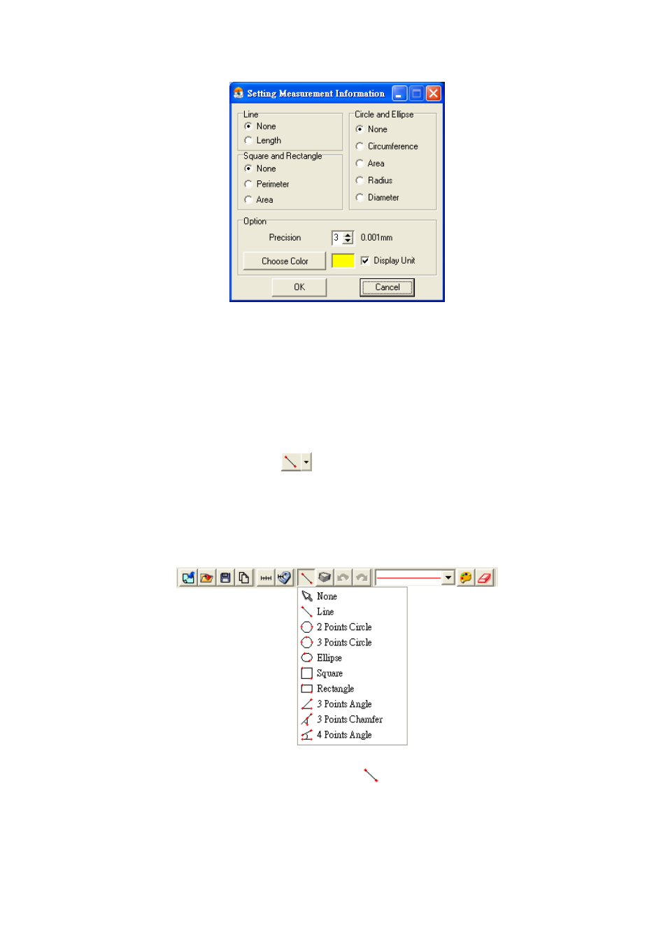
Fig. 5-62. Scale information setting dialog
The “precision” is refers to under the decimal point of effective number of digits. The effective
number of digits can be adjusted. “Choose color” may choose the text color. “Display unit” does not
check its unit “mm” did not display. Attention, after setting option, and also choose the “measuring
means style”.
5.4.7Measurement tool styles 「
」
The measuring include optional Line, 2 Points Circle, 3 Points Circle, Ellipse,
Square, Rectangle, 3 Points Angle, 3 Points Chamfer, 4 Points Angle for variable demand.
Fig. 5-63.
Fig. 5-63. Measurement Tool Styles
(1) Line: Measure the Length and use
. See Fig 5-63.
Firstly choose Fig.5-63 Scale information setting dialog. Measure the Length
on the PCB rectangle, choose the “line” icon, then draw a line, the “ L” means
Length. Ex: L=5.510mm as Fig. 5-64.