Linear vacuum encoder installation, Installation instructions – MicroE 3500V Mercury User Manual
Page 6
Installation Instructions
Linear Encoders
2
Attach the scale to the base
slide. Reference the preferred
datum on the interface drawing
for either end or center index
orientation.
Attach the scale to the slide.
Refer to pg. 8 for details.
Be sure the grating surface of
the scale faces the sensor.
Insure that there is no contact
between these surfaces or
damage may result.
Be sure the source power is off before
connecting the SmartPrecision plug.
Connect the SmartPrecision electronics to the
controller using the pinout diagram described on
the interface drawing.
Pin 1 must not be connected under any
circumstances, including connection to wires
within extension cables and floating wires. Any
connection to Pin 1 could damage or disable the
encoder system.
Insure proper system grounding. Refer to the
procedure on pg 9.
Tighten the thumb screws.
Power up the system. The Power/Calibration
indicator will illuminate.
4
Page 4
3
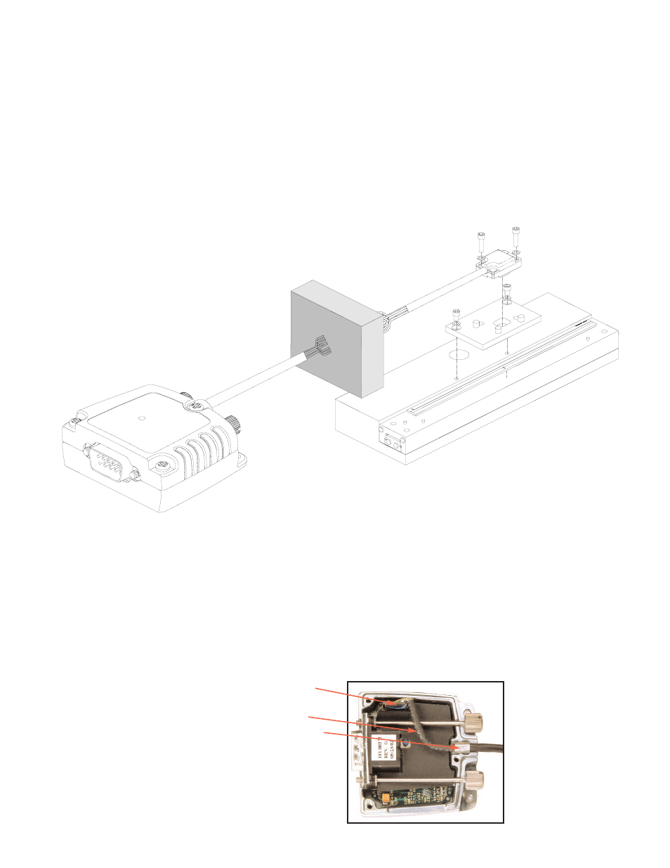
CAUTION: observe precautions for handling electrostatic
sensitive devices.
Install the double shielded “pigtail” cable from vacuum wall to
electronics into the SmartPrecision electronics module. This cable
is shipped with “flying” leads. Customers are responsible for
connector selection and installation.
A) Remove the three cover screws and the top half of the
connector housing. Do not pull on the 15-pin D-sub
connector or the circuit board under the insulation layer.
B) Attach the sensor's 5 X 2 connector to the mating 5 X 2
connector on the circuit board.
C) Route the double shielded “pigtail” cable through its
channel in the center of the connector body and place the
cable's hex sleeve in the matching recess. Attach the top half
of the connector housing to the bottom half using the three
cover screws. The longest screw is used in the hole adjacent
to the cable exit.
D) Connect the customer supplied connector to the feed-through
in the vacuum wall.
Install the sensor on your mounting surface referencing the
appropriate datum surface as shown on the interface
drawing. Use 2 washers per mounting screw.
Benching pins may be used to locate the sensor if the
system mechanical tolerances are adequate. See data sheet
for alignment tolerances, or keep mounting screws loose for
sensor alignment if benching pins are not used.
Connect the vacuum cable to the feed-through in the vacuum
wall. Wires of the same color must be connected through
the vacuum chamber wall (see Interface Drawing for color
assignments). Vacuum cables are shipped with “flying”
leads”. Customers are responsible for connector
selection and installation.
1