Pcm-quad02 block diagram, Software features – Measurement Computing PCM-QUAD02 User Manual
Page 8
PCM-QUAD02 User's Guide
Introducing the PCM-QUAD02
The incremental encoders connect to each channel through either a screw terminal board or a user-configurable,
non-terminated cable. The signals provided are (per channel):
Phase A+, A–
Phase B+, A–
Index+, Index–
+5V and GND (optional power for 5V encoders; not to exceed 400 mA peak)
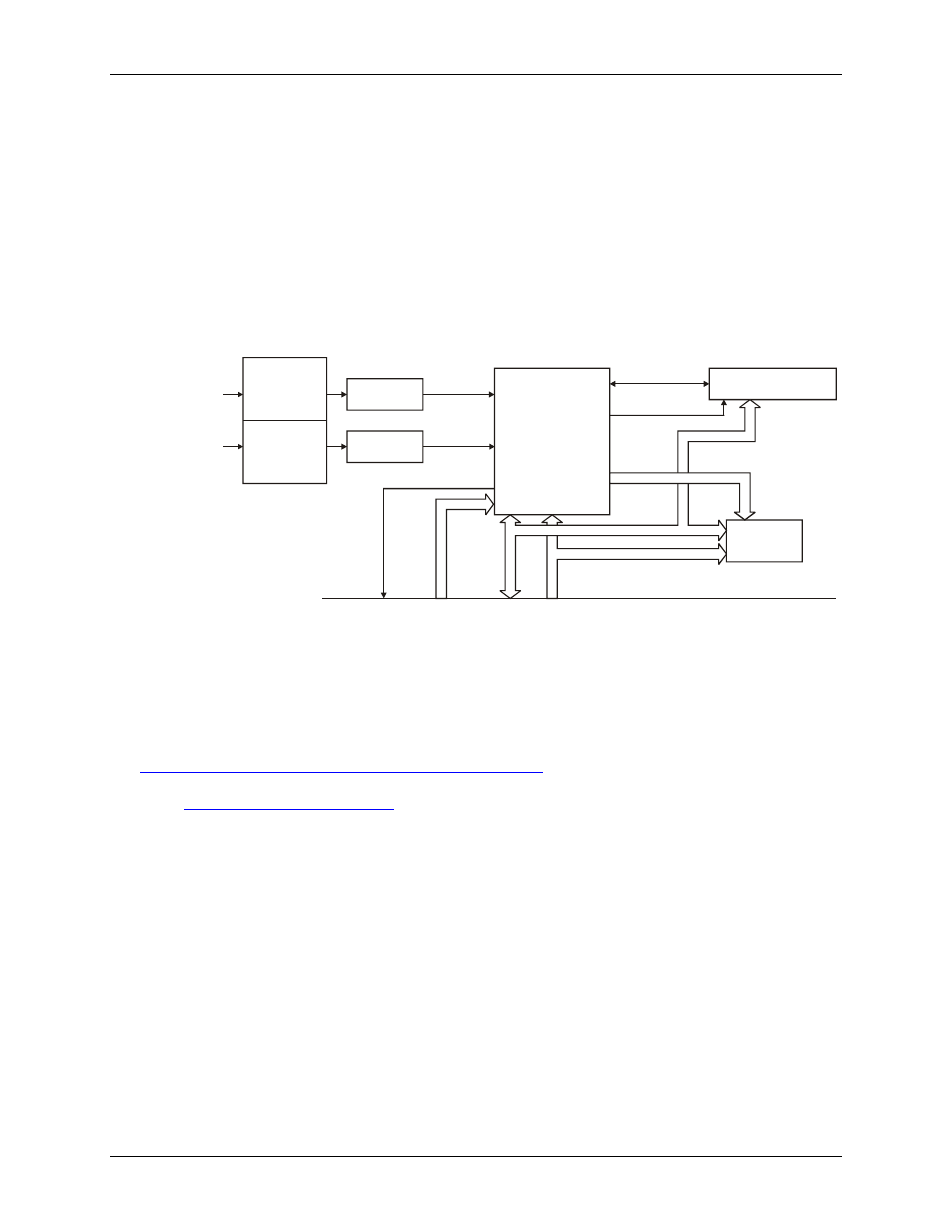
PCM-QUAD02 block diagram
PCM-QUAD02 functions are illustrated in the block diagram shown here.
FPGA
Control
Decode
Signal Routing
CIS
Memory
Channels 1 and 2
PCMCIA bus
Address
Data
Data
Control
Signalling
LS7266: 24 bit dual-axis
quadrature counter
IRQ
Control
75ALS175
75ALS175
Input
Configuration
Quadature
Encoder
Input
Channel
1
Channel
2
S.E./DIFF
Setting
Termination
S.E./DIFF
Setting
Termination
Figure 1. PCM-QUAD02 functional block diagram
Software features
For information on the features of InstaCal and the other software included with your PCM-QUAD02, refer to
the Quick Start Guide that shipped with your device. The Quick Start Guide is also available in PDF at
.
r the latest software version.
7