Pin assignments, Encoder input, Termination resistors – Measurement Computing PCM-QUAD02 User Manual
Page 11: Differential configuration
PCM-QUAD02 User's Guide
Installing the PCM-QUAD02
2. To test your installation and configure your board, run the InstaCal utility you installed in the previous
section. Refer to the Quick Start Guide that came with your board
for information on how to initially set up and load InstaCal.
External connections, input configuration and control
You can connect to the PCM-QUAD02 in one of two ways:
Use a standard AMP 15-pin I/O PCMCIA connector and non-terminated cable, such as the
PCM-C15-10-
INCH
. Details on this product are available on our web site at
Use a standard AMP 15-pin I/O PCMCIA connector with cable which is mated to a screw terminal board,
such as the
PCM-TERM15
. Details on this product are available on our web site at
Pin assignments for both single-ended and differential connections are described below.
Note
Be sure to properly phase the encoder according to the manufacturer’s instructions.
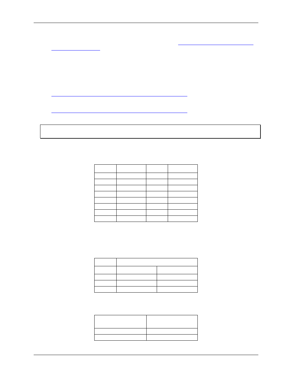
Pin assignments
AMP 15 position I/O connector
Pin #
Function
Pin #
Function
1 Phase
1A+
9 +5
VDC
2
Phase 1A–
10
Phase 2A+
3
Phase 1B+
11
Phase 2A–
4
Phase 1B–
12
Phase 2B+
5
Index 1+
13
Phase 2B–
6
Index 1–
14
Index 2+
7 Ground
15 Index
2–
8 +5
VDC
16
Encoder input
Termination resistors
Footprints provided only.
Resistors
Input
Channel 1
Channel 2
Phase A
R1, 2
R7, 8
Phase B
R3, 4
R9, 10
Index
R5, 6
R11, 12
Differential configuration
The table below lists the default for Phase A signals. The same exist for Phase B and Index signals.
15-pin PCMCIA
Connector
Encoder connection
Phase 1A+
A+
Phase 1A–
A–
10