4 connector diagram – Measurement Computing PPIO-DIO24H User Manual
Page 8
The voltages and currents associated with external devices range from less than a
hundred mA at a few volts for a small flash light bulb to 50 Amps at 220 volts for a
large electric range. Attempting to connect either of these devices directly to the
PPIO-DIO24H would destroy the I/O chip. In these cases, external relays must be
used.
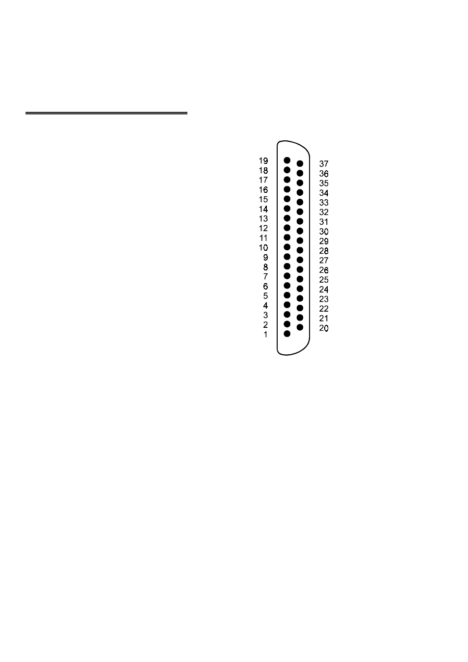
3.4 CONNECTOR DIAGRAM
The PPIO-DIO24H field I/O connector is a
37-pin, D-type connector accessible through
the top cover of the PPIO (Figure 3-2).
The connector accepts female 37-pin, D-type
connectors, such as those on the C37FF-2, a 2
foot cable with connectors.
If frequent changes to signal connections or
signal conditioning is required, please refer to
the information on the CIO-TERMINAL and
CIO-MINI37 screw terminal boards. Contact
Customer Support for assistance in this
important area.
Figure 3-2. I/O Connector
4
PA0
PA1
PA2
PA3
PA4
PA5
PA6
PA7
PC0
PC1
PC2
PC3
PC4
PC5
PC6
PC7
GND
+5V
GND
+5V
GND
NC
GND
NC
GND
NC
GND
PB0
PB1
PB2
PB3
PB4
PB5
PB6
PB7
NC
NC
J1
- ACC-300 (7 pages)
- AI-EXP32 (20 pages)
- AI-EXP48 (19 pages)
- BTH-1208LS (30 pages)
- 6K-ERB08 (32 pages)
- BTH-1208LS Quick Start (4 pages)
- 6K-SSR-RACK08 (33 pages)
- BTH-1208LS-OEM (27 pages)
- CB-COM-Digital (68 pages)
- CB-7018 (68 pages)
- CB-7000 Utilities (44 pages)
- CB-7080D (74 pages)
- CB-COM-7033 (44 pages)
- CB-COM-7017 (72 pages)
- CB-COM-7024 (76 pages)
- CB-NAP-7000P (36 pages)
- CIO-DAC02/16 (16 pages)
- CIO-DAC02 (18 pages)
- CB-NAP-7000D (56 pages)
- CIO-DAC16-I (16 pages)
- CIO-DAC16/16 (20 pages)
- CIO-DAS08 (21 pages)
- CIO-DAC16 (20 pages)
- CIO-DAS08/JR (16 pages)
- CIO-DAS08/JR/16 (14 pages)
- CIO-DAS08/JR-AO (16 pages)
- CIO-DAS08-AOM (32 pages)
- CIO-DAS08-PGM (28 pages)
- CIO-DAS16/330 (34 pages)
- CIO-DAS48-I (17 pages)
- CIO-DAS16/M1 (38 pages)
- CIO-DAS48-PGA (18 pages)
- CIO-DAS800 (20 pages)
- CIO-DAS802/16 (22 pages)
- CIO-DAS6402/16 (40 pages)
- CIO-DAS-TEMP (20 pages)
- CIO-DDA06/16 (18 pages)
- CIO-DDA06/JR (17 pages)
- CIO-DIO24/CTR3 (21 pages)
- CIO-DIO24H (20 pages)
- CIO-DI192 (24 pages)
- CIO-DDA06 (21 pages)
- CIO-DIO48 (19 pages)
- CIO-DO192H (16 pages)
- CIO-DIO192 (20 pages)