2 installing the ppio-dio24h in a laptop, 3 signal connections – Measurement Computing PPIO-DIO24H User Manual
Page 7
6. Route the power cable into the PC through one of the PC's accessory openings in
the back of the PC. Please make sure there are no sharp burrs that may pierce the
cable and cause a short circuit.
7. When the power cable is installed, close your PC and turn on the power.
3.2 INSTALLING THE PPIO-DIO24H IN A LAPTOP
There is no need to turn the Laptop power off.
1. Plug the 25-pin cable into the PC's parallel printer port 1, 2, 3 or 4.
2. Locate the Laptop's mouse connector and install the C-PCPOWER-2M.
mouse-to-power cable (available from Measurement Computing).
3. If you are powering the PPIO-DIO24H from an external power supply, connect the
PPIO Power Cable to the external
power supply.
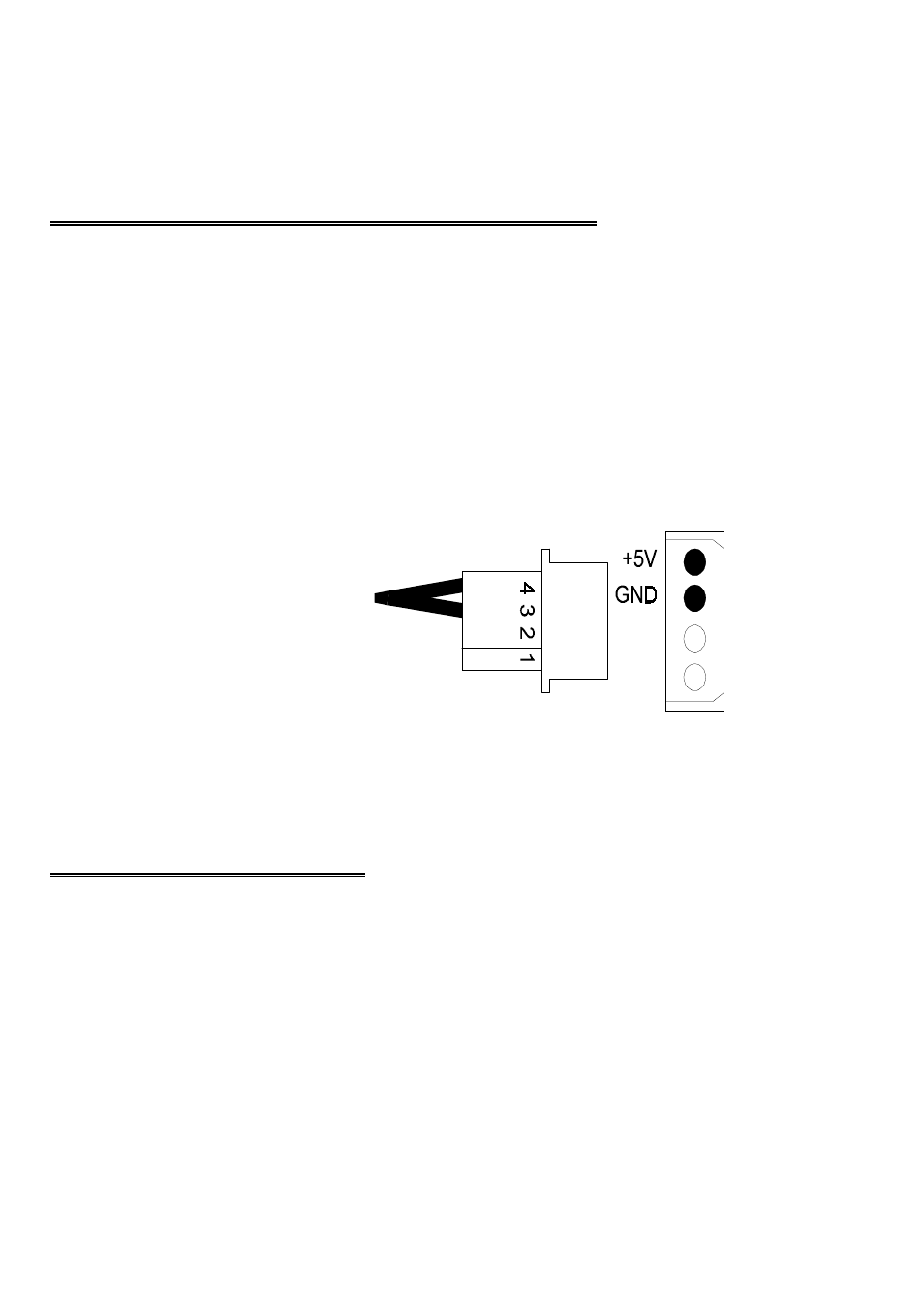
Figure 3-1 shows the power connector
cable from the PPIO-DIO24H. Please
connect only a high quality 5V power
supply, paying close attention to
proper power and ground orientation.
It is not possible to power a PPIO
from the PC via the parallel port.
There are no connections to the power
supply via the parallel port.
Figure 3-1. Power Connector
3.3 SIGNAL CONNECTIONS
The PPIO-DIO24H output signals are buffered (high output drive) TTL. TTL is an
electronics industry term, short for Transistor Transistor Logic, which describes a
standard for digital signals which have two states; near 0V or near 5V.
Under normal operating conditions, the voltages on the pins range from 0 to 0.45 volts
for the low state to between 2.4 to 5.0 volts for the high state.
3