4 digital i/o registers – Measurement Computing PPIO-DIO24H User Manual
Page 11
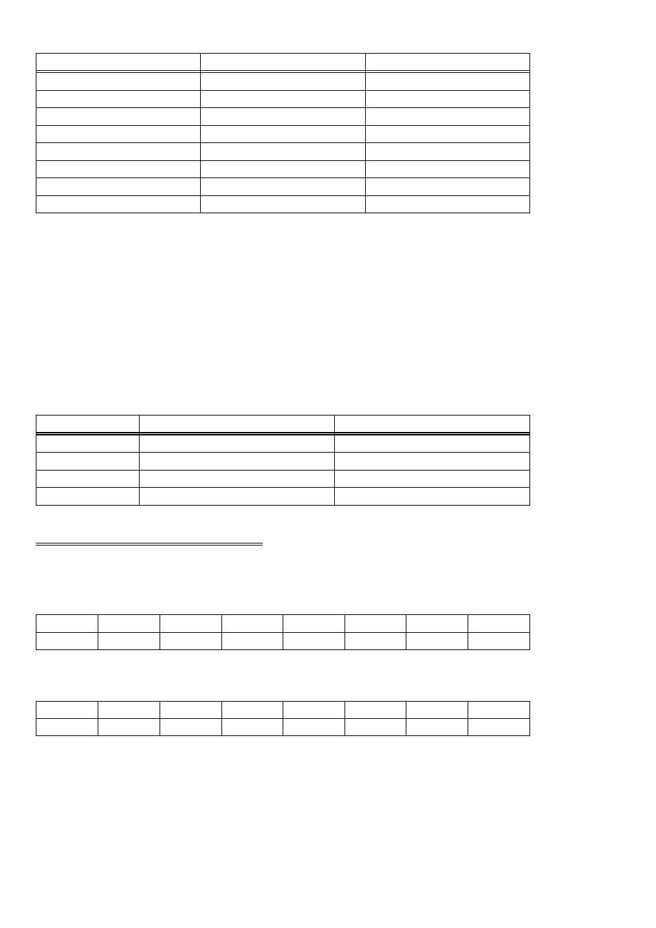
Table 4-1. Bit Weights
80
128
7
40
64
6
20
32
5
10
16
4
8
8
3
4
4
2
2
2
1
1
1
0
HEX VALUE
DECIMAL VALUE
BIT POSITION
To write a control word or data to a register, the individual bits must be set to 0 or 1
then combined to form a byte.
The method of programming required to set/read bits from bytes is beyond the scope
of this manual. It is covered in most Introduction To Programming books.
In summary form, the registers and their function are listed on the following table.
Each register has eight bits which can constitute a byte of data or can be eight
individual bit set/read functions.
Table 4-2. Register Functions
Configure
None. No read back.
3
Port C Outputs
Port C Inputs
2
Port B Outputs
Port B Inputs
1
Port A Outputs
Port A Inputs
0
WRITE FUNCTION
READ FUNCTION
ADDRESS
4.4 DIGITAL I/O REGISTERS
PORT A DATA
A0
A1
A2
A3
A4
A5
A6
A7
0
1
2
3
4
5
6
7
PORT B DATA
B0
B2
B2
B3
B4
B5
B6
B7
0
1
2
3
4
5
6
7
Ports A & B can be programmed as input or output. Each is written to and read from
in bytes. For control and monitoring purposes, individual bits are usually used. Mask
unwanted bits out of reads and writes.
7