Field wiring, signal termination and conditioning, Cable (figure 2-2), Figure 2-3) – Measurement Computing PCI-CTR10 User Manual
Page 12
PCI-CTR10 User's Guide
Installing the PCI-CTR10
Information on signal connections
For general information regarding digital I/O techniques, including signal conditioning and low pass filters,
refer to the Guide to Signal Connections. This document is available on our web site at
).
20
1
37
19
20
1
37
19
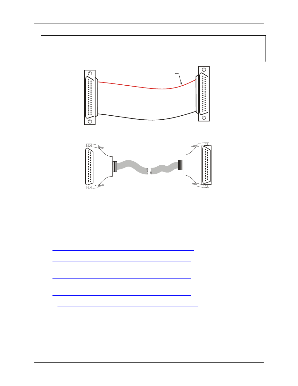
The red stripe
identifies pin # 1
Figure 2-2. C37FF-x cable
20
1
37
19
20
1
37
19
Figure 2-3. C37FFS-x cable
Field wiring, signal termination and conditioning
You can use the following MCC screw terminal boards and relay racks with the PCI-CTR10 board using the
C37FF-x or C37FFS-x cable.
!
SCB37
— 37-conductor, shielded signal connection/screw terminal box that provides two independent 37-
pin connections. Details on this product are available at
.
!
CIO-MINI37
— 4 x 4, 37-pin screw terminal board. Details on this product are available at
!
CIO-MINI37-VERT
— 37-pin screw terminal accessory with vertical 37-pin male D connector. Details on
this product are available on our web site at
!
CIO-TERMINAL
— 16 X 4 universal screw terminal board with on-board prototype area and circuitry.
Details on this product are available on our web site at
!
BP-37/P
— PCI backplate with 37-pin connector/cable. Details on this product are available on our web site
at
.
2-4