Connecting the board for i/o operations, Connectors, cables – main i/o connector, Pinout – main i/o connector – Measurement Computing PCI-CTR10 User Manual
Page 11: Connecting the board for i/o operations -3, Connectors, cables – main i/o connector -3, Table 2-1
PCI-CTR10 User's Guide
Installing the PCI-CTR10
Connecting the board for I/O operations
Connectors, cables – main I/O connector
Table 2-1. Board connectors, cables, accessory equipment
lists the board connectors, applicable cables and compatible accessory boards.
Connector type
!
P1: 37-pin shielded, D-type, right angle
!
P2: 37-pin unshielded, D-type, straight
Compatible cables
C37FF-x, unshielded ribbon cable (Figure 2-2)
C37FFS-x, shielded round cable (Figure 2-3)
Compatible accessory
products
CIO-MINI37
CIO-MINI37-VERT
CIO-TERMINAL
SCB-37
BP-37/P (Note 1)
Note 1: The BP-37/P is required to cable all CTR B signals from connector P2 to the PC bulkhead.
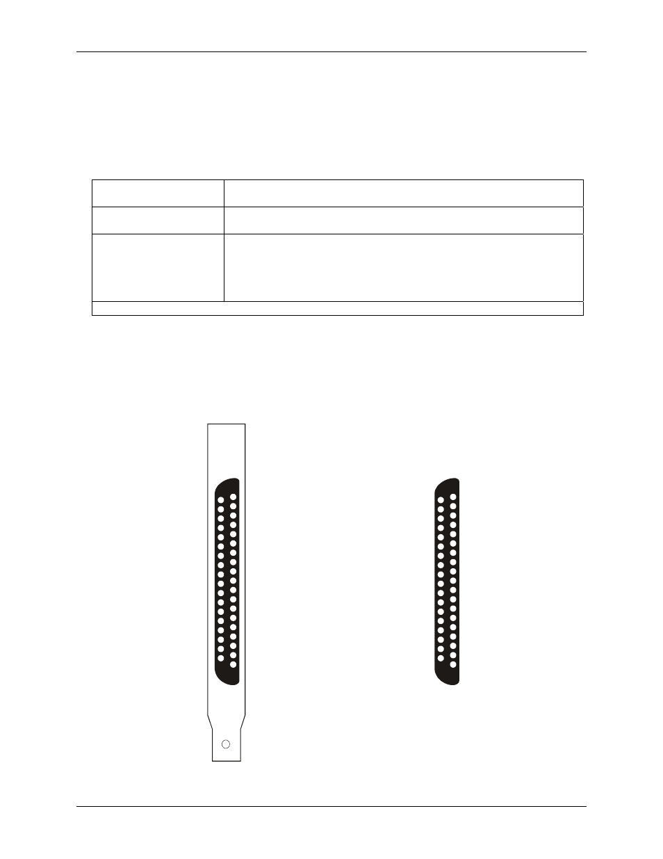
Pinout – main I/O connector
The PCI-CTR10 has two male, 37-pin D-type connector -
P1
and
P2
(see
.) Digital input, digital
output and interrupt signals from the 9513 are all accessible on these connectors.
Figure 2-1. Board connectors P1 and P2
The signals on both connectors are identical. The second 9513 device on the PCI-CTR10 is accessible via
connector P2 at the rear of the board, and is wired identically to the 9513 device on connector P1.
CTR1GATE_A
CTR1CLK_A
CTR1OUT_A
CTR2OUT_A
CTR3OUT_A
CTR4OUT_A
CTR5OUT_A
OSC OUT_A
DIN0_A
DIN1_A
DIN2_A
DIN3_A
DIN4_A
DIN5_A
DIN6_A
DIN7_A
DIN STROBE_A
PC +5V
CTR2CLK
_A
CTR2GATE
_A
CTR3CLK
_A
CTR3GATE
_A
CTR4CLK
_A
CTR4GATE
_A
CTR5CLK
_A
CTR5GATE
_A
GND
D
0
OUT _A
D
1
OUT _A
D
2
OUT _A
D
3
OUT _A
D
4
OUT _A
DOUT7_A
P1 (Counter A)
CTR1GATE_B
CTR1CLK_B
CTR1OUT_B
CTR2OUT_B
CTR3OUT_B
CTR4OUT_B
CTR5OUT_B
OSC OUT_B
DIN0_B
DIN1_B
DIN2_B
DIN3_B
DIN4_B
DIN5_B
DIN6_B
DIN7_B
DIN STROBE_B
PC +5V
P2 (Counter B)
DOUT6_A
DOUT5_A
IRQ_A INPUT
IRQ_A ENABLE
CTR2CLK
_B
CTR2GATE
_B
CTR3CLK
_B
CTR3GATE
_B
CTR4CLK
_B
CTR4GATE
_B
CTR5CLK
_B
CTR5GATE
_B
GND
D
0
OUT _B
D
1
OUT _B
D
2
OUT _B
D
3
OUT _B
D
4
OUT _B
D
5
OUT _B
D
6
OUT _B
D
7_B
OUT
IRQ_B INPUT
IRQ_B ENABLE
1
2
3
4
5
6
7
8
9
10
11
12
13
14
15
16
17
18
19
20
21
22
23
24
25
26
27
28
29
30
31
32
33
34
35
36
37
20
21
22
23
24
25
26
27
28
29
30
31
32
33
34
35
36
37
1
2
3
4
5
6
7
8
9
10
11
12
13
14
15
16
17
18
19
2-3