Output (sink) current limits, Output (source) current limits, Power terminals – Measurement Computing USB-1096HFS User Manual
Page 17: Power terminals -4
USB-1096HFS User's Guide
Functional Details
!
Connect up to 24 FOURTHPORT signals to the screw terminals labeled
PORT 4
.
You can configure each digital port for either input or output.
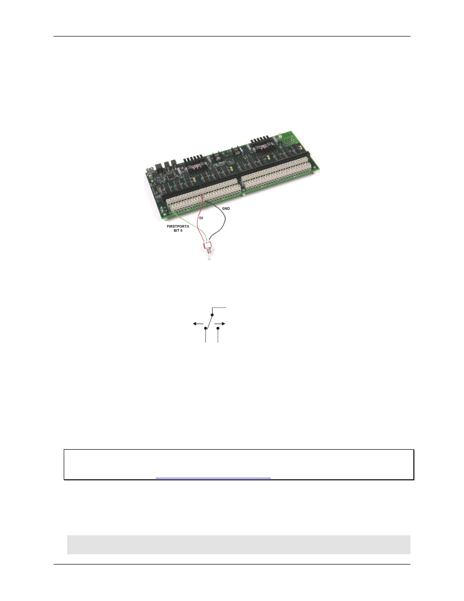
When configured for input, you can use the USB-1096HFS digital I/O terminals to detect the state of any TTL
level input.
shows the USB-1096HFS wired to detect the state of a switch. When you set the switch
to the
+5 V
position, FIRSTPORTA Bit 0 reads TRUE (1). When you move the switch to the
GND
position,
FIRSTPORTA Bit 0 reads FALSE (0).
Figure 3-2. Digital connection of FIRSTPORTA Bit 0 detecting the state of a switch
A schematic drawing of this switch connection is shown here.
+5V
+GND
FIRSTPORTA Bit 0
Figure 3-3. Schematic showing switch connection to digital channel FIRSTPORTA Bit 0
Output (sink) current limits
Each DIO pin can sink 64 mA maximum when configured for output.
Output (source) current limits
Each DIO pin can source 24 mA maximum when configured for output. The USB-1096HFS can source a
maximum 2.6 A, total.
For more information on digital signal connections
For information on digital signal connections and I/O techniques, refer to the Guide to Signal Connections
(available on our web site at
).
Power terminals
The USB-1096HFS has three +5 V power output terminals. Each power output terminal is labeled
5V
. A total of
50 mA may be drawn from the 3 terminals.
Caution! Each
5V
power terminal is an output. Do not connect to an external power supply or you may
damage the USB-1096HFS and possibly the computer.
3-4