Functional details, Internal components, Usb out connector – Measurement Computing USB-1096HFS User Manual
Page 14: Usb in connector, Functional details -1, Internal components -1, Usb out connector -1, Usb in connector -1, Chapter 3
Chapter 3
Functional Details
Internal components
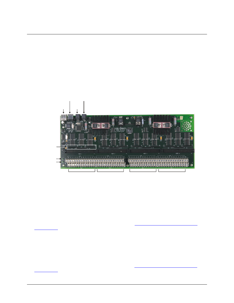
These USB-1096HFS components are shown in Figure 3-1.
!
Two (2) USB connectors
!
Two (2) external power connectors
!
USB LED
!
PWR LED
!
12 pull-up/pull-down resistors
!
Four (4) screw terminal banks (Port 1 through Port 4)
Port 1
USB IN
POWER
OUT
POWER IN
USB
OUT
Port 2
Port 3
Port 4
PWR LED
USB LED
Pull-up/down
SIP resistors
Figure 3-1. USB-1096HFS components
USB OUT connector
The
USB OUT
connector is a downstream hub output port intended for use with other MCC USB Series
products only. The USB hub is self-powered, and can provide 100 mA maximum current at 5 V. The USB out
connector is labeled
USB OUT
on the enclosure and
J2
on the board.
When connecting to another MCC USB Series product, connect the
USB OUT
connector on the USB-1096HFS
to the
USB IN
connector on the next device in the chain. Refer to
Daisy chaining additional modules to the
on page 3-5 for information on how to connect multiple MCC USB Series products.
USB IN connector
Connect the
USB IN
connector to the USB port on your computer (or USB hub connected to your computer)
using the supplied USB cable. The USB in connector is labeled
USB IN
on the enclosure and
J1
on the board.
When connecting to another MCC USB Series product, connect the
USB IN
connector on the USB-1096HFS to
the
USB OUT
connector on the next device in the chain Refer to
Daisy chaining additional modules to the
on page 3-5 for more information on how to connect multiple MCC USB Series products.
3-1