Cabling, Field wiring, signal termination and conditioning, Cabling -5 – Measurement Computing PCI-CTR20HD User Manual
Page 13: Le (figure 2-2), Error! reference source not found
PCI-CTR20HD User's Guide
Installing the PCI-CTR20HD
Cabling
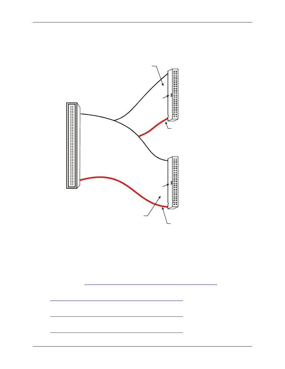
Use a C100FF-x 100-pin cable to connect signals to the CTR20HD board. This cable consists of two 50-pin
ribbon cables that are joined together at a 100-pin high density header connector (
.)
Figure 2-2. C100FF-x cable
1
50
2
49
51
100
52
99
100
50
51
1
Key
Key
The red stripe
identifies pin # 1
The red stripe
identifies pin # 51
Cable is labeled
“Pins 51-100”
Cable is labeled
“Pins 1-50”
Field Wiring connections:
CIO-MINI50
CIO-MINI50/DST
CIO-TERM100
CIO-TERM100/DST
CIO-SPADE50
SCB-50
Field Wiring connections:
CIO-MINI50
CIO-MINI50/DST
CIO-TERM100
CIO-TERM100/DST
CIO-SPADE50
SCB-50
Field wiring, signal termination and conditioning
You can use the following MCC screw terminal boards to terminate field signals and route them into the PCI-
CTR20HD board using the C100FF-x cable:
!
CIO-MINI50 – 50-pin screw terminal board. Two boards are required. Details on this product are available
on our
!
CIO-MINI50/DST – 50-pin screw terminal board with detachable screw terminals. Two boards are
required. Details on this product are available on our web site at
!
CIO-TERM100 – 100-pin screw terminal board (daisy-chained 50-pin IDC connectors). Details on this
product are available on our web site at
!
CIO-TERM100/DST – 100-pin screw terminal board with detachable screw terminals (daisy-chained
50-pin IDC connectors). Details on this product are available on our web site at
2-5