2 low pass filters de-bounce inputs – Measurement Computing CIO-CTRxxHD User Manual
Page 15
NOTE
The resistors, R1 and R2, are going to dissipate power in the divider
circuit according to the equation W = I
2
x R; (Current (I) =
Voltage/Resistance). The higher the value of the resistance (R1 +
R2), the less power dissipated by the divider circuit. Here is a
simple rule:
For attenuation of <5:1, no resistor should be less than 10K.
For attenuation of > 5:1, no resistor should be less than 1K.
The CIO-TERMINAL has the circuitry on board to create custom voltage dividers.
The CIO-TERMINAL is a 16" by 4" screw terminal board with two 37 pin D type
connectors and 56 screw terminals (12 - 22 AWG). Designed for table top, wall or
rack mounting, the board provides prototype, divider circuit, filter circuit and pull-up
resistor positions which you may complete with the proper value components for your
application.
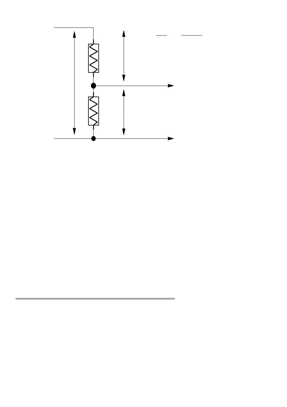
7.2
LOW PASS FILTERS DE-BOUNCE INPUTS
A low pass filter is placed on the signal wires between a signal and an A/D board. It
prevents frequencies greater than the cut-off frequency from entering the A/D board's
digital inputs.
11
SIGNAL HIGH
SIGNAL LOW
R1
R2
A/D BOARD
HIGH INPUT
A/D BOARD
LOW INPUT
SIGNAL
VOLTS
V1
V2
Vout
Vin
=
R1 + R2
R2
Vin
Vout
SIMPLE VOLTAGE DIVIDER