Measurement Computing CIO-CTRxxHD User Manual
Page 10
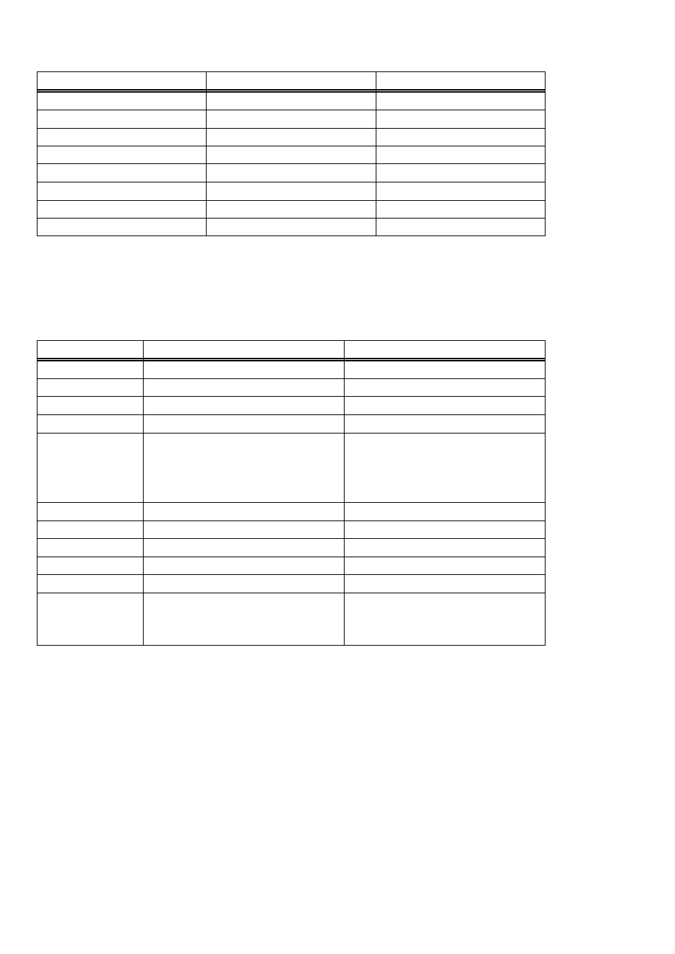
To write to or read from a register in decimal or HEX, the following weights apply:
80
128
7
40
64
6
20
32
5
10
16
4
8
8
3
4
4
2
2
2
1
1
1
0
HEX VALUE
DECIMAL VALUE
BIT POSITION
In summary form, the registers and their function are listed on the following table.
Within each register are eight bits which may constitute a byte of data or eight
individual bit functions.
Table 5-1. Register Functions
Interrupt and Counter Source
for 9513 #3 and 9513 #4 (2nd
ten channels on P2)
No read function.
BASE +401h
Commands to 9513 #4
Status of 9513 #4
BASE +7
Data for 9513 #4
Data from 9513 #4
BASE +6
Commands to 9513 #3
Status of 9513 #3
BASE +5
Data for 9513 #3
Data from 9513 #3
BASE +4
Additional for CTR20 only
Wait State, Interrupt and
Counter Source for 9513 #1
and 9513 #2 (1st ten channels
on P1)
No read function.
BASE +400h
Commands to 9513 #2
Status of 9513 #2
BASE +3
Data for 9513 #2
Data from 9513 #2
BASE +2
Commands to 9513 #1
Status of 9513 #1
BASE +1
Data for 9513 #1
Data from 9513 #1
BASE +0
WRITE FUNCTION
READ FUNCTION
ADDRESS
9513 #1 (U1) is accessed at the bottom half of P1 (pins 1 - 22);
9513 #2 (U2) is the top half of P1 (pins 27 - 48);
9513 #3 (U3) is accessed at the bottom half of P2 (pins 1 - 22);
9513 #4 (U4) is the top half of P2 (pins 27 - 48).
6