3 front panel indicators, 4 line voltage selection, Extender488/hs – Measurement Computing Extender 488HS Rev.2.0 User Manual
Page 11
Section 2
Getting Started
2.3
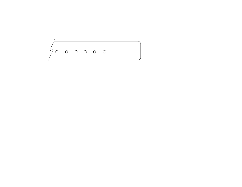
2.3 Front Panel Indicators
Six LEDs on the front panel of the Extender488/HS display the status of the bus
extender. The function of each indicator is described below.
LOCAL
EXTENDER
CONNECT
LISTEN
POWER
TALK
REMOTE
EXTENDER
Extender488/HS
HIGH SPEED BUS EXTENDER
Front Panel Indicators
LOCAL
ON when the Extender488/HS is configured as the Local EXTENDER
Extender.
REMOTE
ON when the Extender488/HS is configured as the EXTENDER
Remote Extender.
CONNECT
ON if both Extender488/HS Bus Extenders are powered
on and the interconnecting cable is functional.
TALK
Remote Extender - On when a device on the Local bus (or the
controller) is talking to device(s) on the Remote bus.
Local Extender - On except when a device on the Local bus (or the
controller) is talking to device(s) on the Remote bus.
LISTEN
Local Extender - On when a device on the Local bus (or the controller)
is talking to device(s) on the Remote bus.
Remote Extender - On except when a device on the Local bus (or the
controller) is talking to device(s) on the Remote bus.
POWER
ON when power is applied to the Extender488/HS and the power
switch on the rear panel is in the ON position (depressed). OFF
otherwise.
2.4 Line Voltage Selection
The line voltage is set by an internal switch (S3) located near the rear panel power supply
connector, next to the power switch. To change the operating voltage, it is necessary to open the enclosure