P2 - digital i/o, Daqbook p2 pinout digital i/o – Measurement Computing 200 Series DaqBook User Manual
Page 28
3-10 DaqBook Hardware
01-23-02
DaqBook User’s Manual
DaqBook
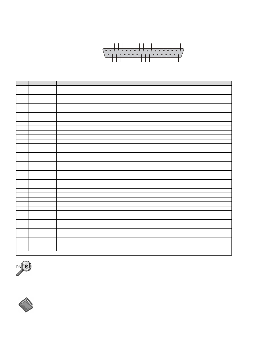
P2 Pinout
Digital I/O
This P2 interface is
available on the
DaqBook/100, /120,
/200, and /260.
1
9
G
N
D
P
O
R
T
A
0
3
7
P
O
R
T
A
1
3
6
P
O
R
T
A
2
3
5
P
O
R
T
A
3
3
4
P
O
R
T
A
4
3
3
P
O
R
T
A
5
3
2
P
O
R
T
A
6
3
1
P
O
R
T
A
7
3
0
P
O
R
T
C
0
2
9
P
O
R
T
C
1
2
8
P
O
R
T
C
2
2
7
P
O
R
T
C
3
2
6
P
O
R
T
C
4
2
5
P
O
R
T
C
5
2
4
P
O
R
T
C
6
2
3
P
O
R
T
C
7
2
2
G
N
D
2
1
+
5
V
2
0
8
P
O
R
T
B
2
7
P
O
R
T
B
3
6
P
O
R
T
B
4
5
P
O
R
T
B
5
4
P
O
R
T
B
6
3
P
O
R
T
B
7
2
I
R
E
N
A
B
L
E
1
IR
I
N
P
U
T
1
0
P
O
R
T
B
0
9
P
O
R
T
B
1
1
8
+
5
1
7
G
N
D
1
6
N
/C
1
5
G
N
D
1
4
N
/C
1
3
G
N
D
1
2
N
/C
11
G
N
D
Pin
Signal Name
Description for P2 Pin Use
1
IR INPUT
Interrupt line input (no functions to access this)
2
IR ENABLE
Interrupt line enable (no functions to access this)
3
PORT B 7
Digital input/output - port B bit 7
4
PORT B 6
Digital input/output - port B bit 6
5
PORT B 5
Digital input/output - port B bit 5
6
PORT B 4
Digital input/output - port B bit 4
7
PORT B 3
Digital input/output - port B bit 3
8
PORT B 2
Digital input/output - port B bit 2
9
PORT B 1
Digital input/output - port B bit 1
10
PORT B 0
Digital input/output - port B bit 0
11
GND
Digital ground
12
N/C
Pin not connected/not used
13
GND
Digital ground
14
N/C
Pin not connected/not used
15
GND
Digital ground
16
N/C
Pin not connected/not used
17
GND
Digital ground
18
+5 V
+5 V supply
see Note 1
19
GND
Digital ground
20
+5 V
+5 V supply
see Note 1
21
GND
Digital ground
22
PORT C 7
Digital input/output - port C bit 7
23
PORT C 6
Digital input/output - port C bit 6
24
PORT C 5
Digital input/output - port C bit 5
25
PORT C 4
Digital input/output - port C bit 4
26
PORT C 3
Digital input/output - port C bit 3
27
PORT C 2
Digital input/output - port C bit 2
28
PORT C 1
Digital input/output - port C bit 1
29
PORT C 0
Digital input/output - port C bit 0
30
PORT A 7
Digital input/output - port A bit 7
31
PORT A 6
Digital input/output - port A bit 6
32
PORT A 5
Digital input/output - port A bit 5
33
PORT A 4
Digital input/output - port A bit 4
34
PORT A 3
Digital input/output - port A bit 3
35
PORT A 2
Digital input/output - port A bit 2
36
PORT A 1
Digital input/output - port A bit 1
37
PORT A 0
Digital input/output - port A bit 0
Note: No local lines are available if digital expansion cards are in use.
P2 expansion cables must be kept short for proper operation. Do not exceed 14” per attached DBK card.
Note 1: Refer to the
Power Management
section in the DBK options manual (p/n 457-0905).
Reference Note:
The
Power Management section of the DBK Option Cards and Modules User’s Manual
(p/n 457-0905) contains
additional power-related information. As a part of product support, this manual is automatically loaded onto your
hard drive during software installation. The default location is the Programs directory, which can be accessed
through the Windows Desktop.