4 line voltage selection – Measurement Computing Isolator488 User Manual
Page 16
Section 2
Getting Started
2.7
2. To connect the Instrument Common to earth ground, insert a 1/2 amp fuse in the
fuse clips labelled F3. Make note of this change for later reference.
3. To connect pin 12 (shield) of the Instrument Port to Instrument Common, solder
a bare jumper wire in the location labeled JPR2. Make note of this change for later
reference.
After making any changes to the Isolator488 internal circuitry, be sure to
document your changes then carefully reassemble the unit.
2.4
Line Voltage Selection
The Isolator 488 is designed to accept either 105 to 125 volt or 210 to 250
volt, 50 or 60 Hz, AC power. Each unit, when shipped from the factory, is labeled
with its input voltage setting. If this setting is not appropriate, the internal voltage
selection witch must be changed. Failure to operate the Isolator488 from
appropriate power source may result in damage to the unit. To check or change the
voltage selection switch disconnect all cables from the Isolator488 and follow the
steps below.
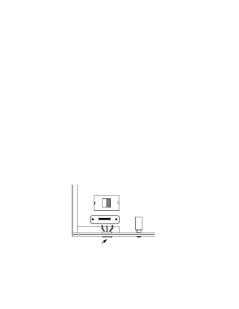
Isolator Fuse and Line Voltage Switch Locations
F1
S2
S1
WARNING :
LETHAL VOLTAGES
MAY BE PRESENT
115V
Power Connector