3 - thermocouple input, Wiring, Thermocouple input 3 – Measurement Computing 6222 User Manual
Page 13
6222
User’s Manual
Thermocouple Input 3-1
Thermocouple Input 3
Wiring …… 3-1
Circuitry …… 3-2
Accuracy
…… 3-2
Accuracy for Different Thermocouple Types …… 3-2
Cold-
Junction Temperature Accuracy …… 3-4
Minimizing Thermal Gradients ...... 3-4
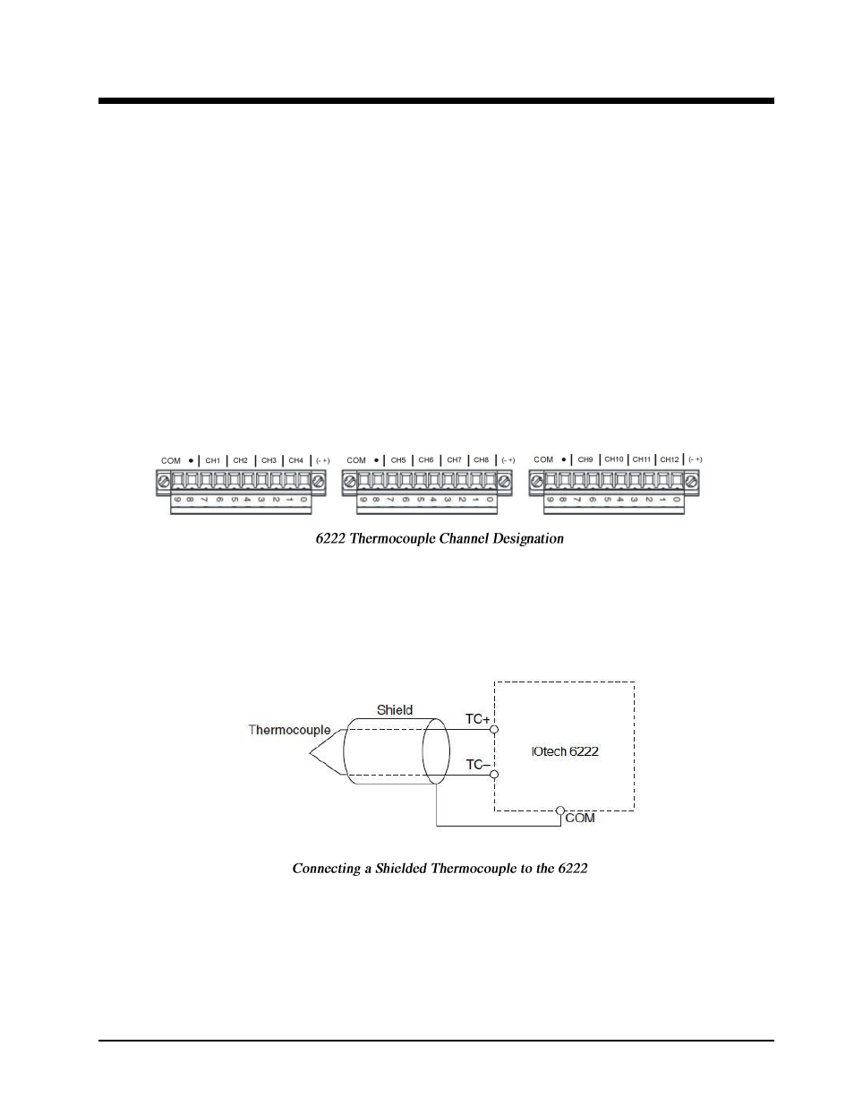
Wiring
The 6222 has three 10-terminal, detachable screw-terminal connectors. Each of the three connectors supports
four thermocouple input channels. Each channel has a terminal to which you can connect the positive lead of
the thermocouple, TC+, and a terminal to which you can connect the negative lead of the thermocouple, TC–.
For each set of four channels (Channels 1 through 4, 5 through 8, and 9 through 12) the 6222 has a common
terminal (COM) that is internally connected to the isolated ground reference of the module. The following
figure shows the terminal assignments for each channel. Odd numbered terminals are negative (-) and even
numbered terminals are positive (+).
When connecting thermocouple input signals to the 6222, connect the positive lead of the thermocouple to the
TC+ terminal and the negative lead to the TC– terminal. If you are unsure which of the thermocouple leads is
positive and which is negative, check the thermocouple documentation or the thermocouple wire spool. If you
are using shielded wiring, connect one end of the shield to the COM terminal as indicated in the following
figure.