Specifications, I/o module configuration, Power – Measurement Computing USB-SSR08 User Manual
Page 19: External power input, Specifications -1, I/o module configuration -1, Power -1, External power input -1
Chapter 4
Specifications
Typical for 25 °C unless otherwise specified.
Specifications in italic text are guaranteed by design.
I/O module configuration
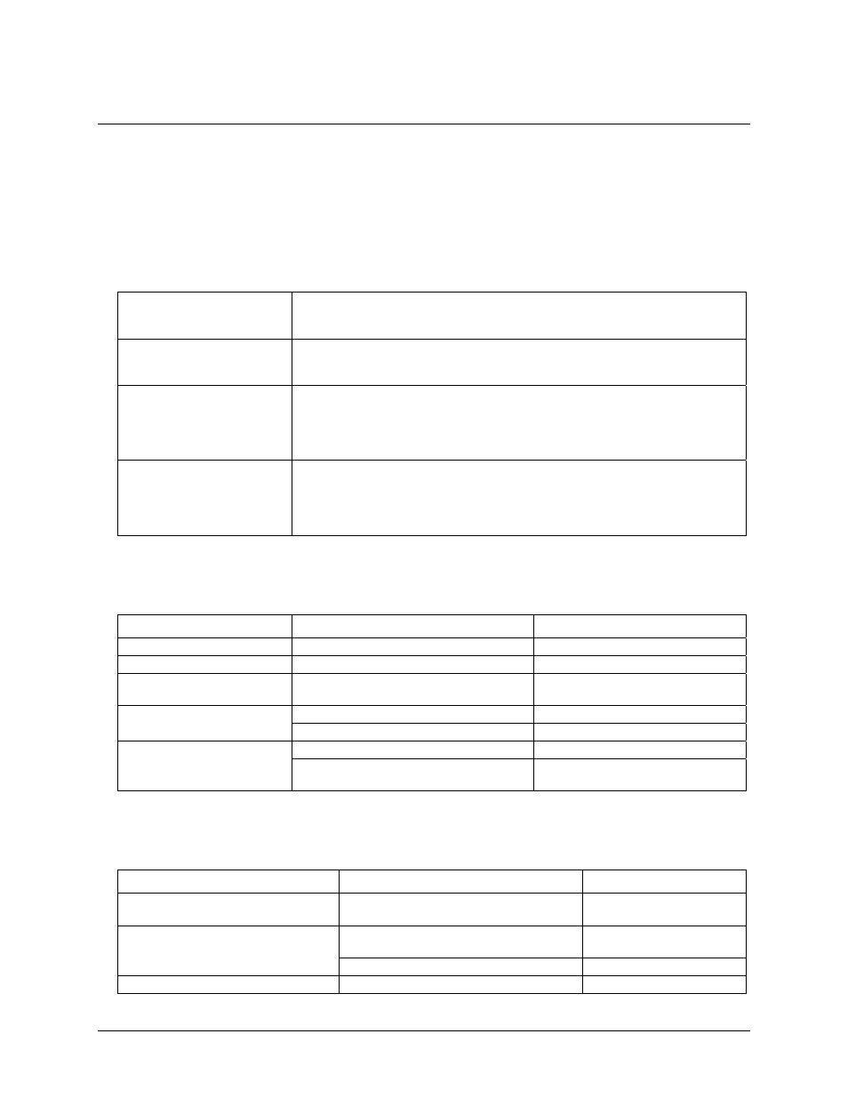
Table 1. I/O module configuration specifications
Modules 1-4
User-selectable via switch S1 "CL" position as either input modules or output (default)
modules. Switch settings for direction can be read back via software. Do not mix input
and output modules within this bank of four.
Modules 5-8
User-selectable via switch S1 "CH" position as either input modules or output (default)
modules. Switch settings for direction can be read back via software. Do not mix input
and output modules within this bank of four.
Pull-up/pull-down on digital
I/O lines
Configurable via switch S3 with 2.2 K ohm resistor network. Switch settings for pull-
up/pull-down selection can be read back via software. Default to pull-up. Switch
settings are applicable during power up conditions of output modules only. Modules are
active Low. When switch to Pull-up, modules are inactive on power up. When switched
to pull-down, modules are active on power up.
I/O module logic polarity
Selectable via switch S2. Switch settings for polarity can be read back via software.
Default to non-inverted. For input modules, invert mode returns a “1” when module is
active; non-invert mode returns a “0” when module is active. For output modules,
invert mode allows users to write a "1" to activate the module; non-invert mode allows
users to write a "0" to activate the module.
Power
Table 2. Power specifications
Parameter Conditions
Specification
USB +5 V input voltage range.
4.75 V min. to 5.25 V max.
USB +5 V supply current
All modes of operation
<100 mA
External power supply
(included)
MCC p/n CB-PWR-9
9 V ± 10% @ 1.0 A
6.0 V > V
ext
> 12.5 V
PWR LED = Off (power fault)
Voltage supervisor limits -
PWR LED
6.0 V < V
ext
< 12.5 V
PWR LED = On
All modules off, 0 A downstream hub power
180 mA typ, 220 mA max.
External power consumption
All modules on, 100 mA downstream hub
power
300 mA typ, 360 mA max.
External power input
Table 3. External power input specifications
Parameter Conditions
Specification
External power input
+6.0 VDC to 12.5 VDC (9
VDC power supply included)
6.0 V > Vext or Vext > 12.5 V
PWR LED = Off (power
fault)
Voltage supervisor limits - PWR LED.
(Note 1)
6.0 V < Vext < 12.5 V
PWR LED = On
External power adapter (included)
MCC p/n CB-PWR-9
+9 V ±10%, @ 1.0 A
4-1