Functional details, Internal components, Usb in connector – Measurement Computing USB-SSR08 User Manual
Page 15: Usb out connector, Functional details -1, Internal components -1, Usb in connector -1, Usb out connector -1, Gure 3-1, Chapter 3
Chapter 3
Functional Details
Internal components
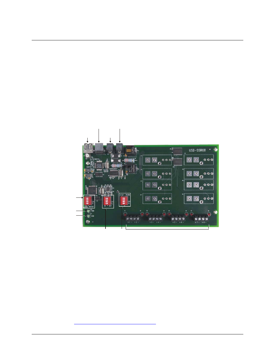
The USB-SSR08 has the following internal components, as shown in Figure 3-1.
Two (2) USB connectors
Two (2) external power connectors
PWR LED
USB LED
I/O module type switch (
S1
)
Control logic polarity switch (
S2
)
Power-up state configuration switch (
S3
)
Screw terminals (eight pairs)
PWR LED
USB LED
USB IN
POWER
OUT
POWER IN
USB
OUT
Control logic
polarity switch
(S2)
I/O
module type
switch (S1)
Power-up state
configuration
switch (S3)
Screw terminals
Figure 3-1. USB-SSR08 components
USB in connector
The USB in connector is labeled
USB IN
on the enclosure and on the board. This connector is a USB 2.0 full-
speed input connector that you connect to the USB port on your computer (or USB hub connected to your
computer). This connector supports USB 1.1, USB 2.0 devices.
USB out connector
The USB out connector is labeled
USB OUT
on the enclosure on the board. This connector is a downstream hub
output port intended for use with other MCC USB Series products only. The USB hub is self-powered, and can
provide
100 mA
maximum current at 5 V. For information on daisy chaining to other MCC USB Series
products, refer to "
Daisy chaining multiple USB-SSR08 devices
3-1