I/o module type, Control logic polarity, Relay power-up state – Measurement Computing USB-SSR08 User Manual
Page 12
USB-SSR08 User's Guide
Installing the USB-SSR08
Remove from the enclosure to access the on-board switches
To change the configuration of a switch, you must first remove the USB-SSR08 from the enclosure. Turn
external power off before changing the switch settings
I/O module type
Configure switch
S1
to set the type of each module group for input or output. By default switch S1 is shipped
with all modules configured for output, as shown in
Figure 2-2. I/O module type switch (S1)
CH
CL
OUT
IN
S1
You cannot mix input and output modules within a group.
Control logic polarity
Configure switch
S2
to set the control logic polarity for each module group for inverted (active high) or non-
inverted (active low, default) logic. By default, this switch is shipped with all banks configured for non-inverted
logic, as shown in Fi
Figure 2-3. Relay logic switch (S2)
CH
CL
INVERT
NON
INVERT
S2
For input modules,
invert
mode returns a "1" when the modules are active.
Non-invert
mode returns a "0"
when the modules are active.
For output modules,
invert
mode allows you to write a "1" to activate the module.
Non-invert
mode allows
you to write a "0" to activate the module.
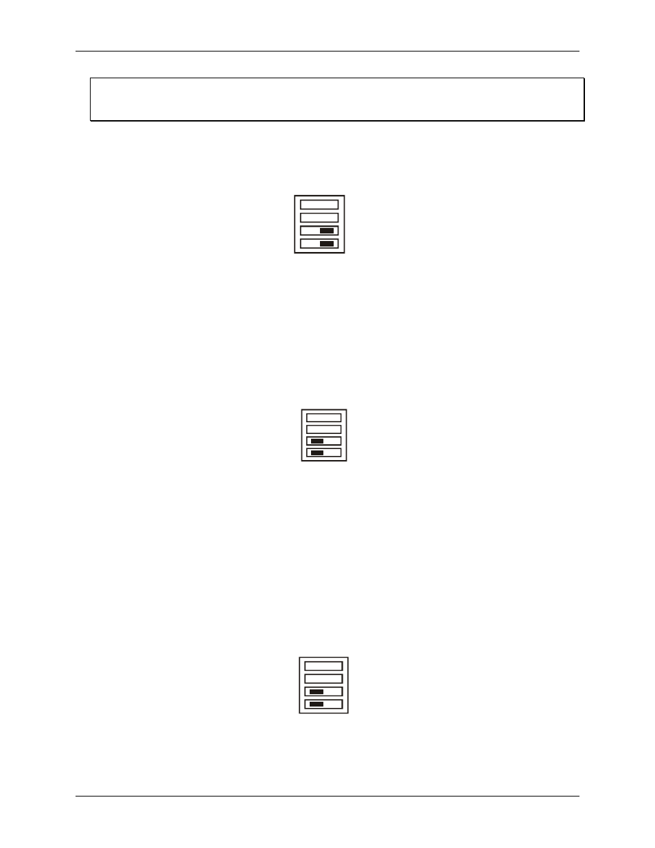
Relay power-up state
Configure switch
S3
to set the state of the output relays at power-up. By default, this product is shipped with the
switch for all banks configured for pull-up (modules inactive on power-up), as shown in
. When
switched to
P/DN
(pull-down), modules are active on power-up. Switch settings can be read back via software.
Figure 2-4. Relay power-up state switch (S3)
CH
CL
P/DN
P/UP
S3
2-3