Measurement Computing USB-5203 User Manual
Page 31
USB-5203 User's Guide
Specifications
31
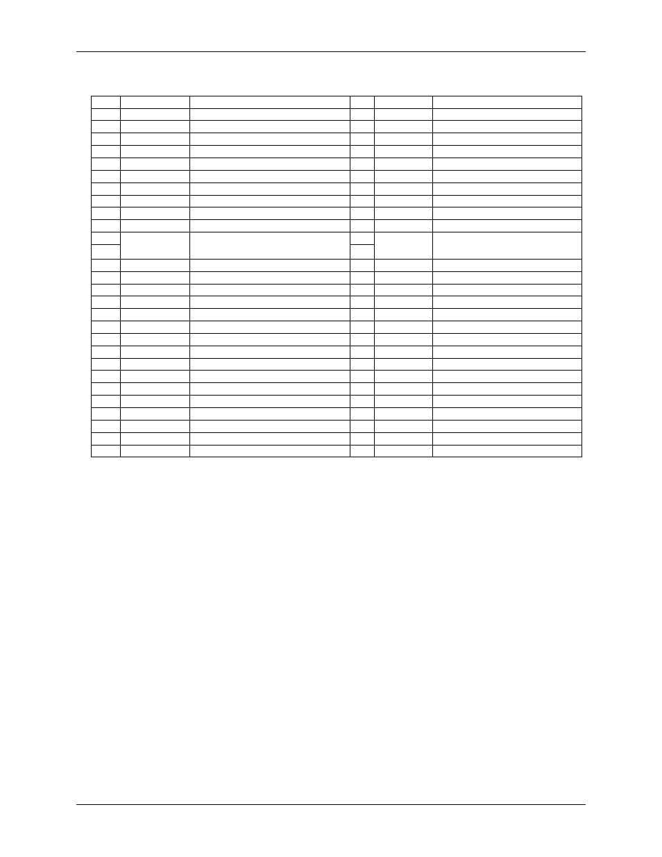
Table 23. Screw terminal pinout
Pin
Signal Name
Pin Description
Pin Signal Name Pin Description
1
I1+
CH0/CH1 current excitation source
27
I4–
CH6/CH7 current excitation return
2
NC
No connection
28
GND
Ground
3
C0H
CH0 sensor input (+)
29
C7L
CH7 sensor input (–)
4
C0L
CH0 sensor input (–)
30
C7H
CH7 sensor input (+)
5
4W01
CH0/CH1 4-wire, 2 sensor common
31
IC67
CH6/CH7 2 sensor common
6
IC01
CH0/CH1 2-sensor common
32
4W67
CH6/CH7 4-wire, 2 sensor common
7
C1H
CH1 sensor input (+)
33
C6L
CH6 sensor input (–)
8
C1L
CH1 sensor input (–)
34
C6H
CH6 sensor input (+)
9
GND
Ground
35
NC
No connection
10
I1–
CH0/CH1 current excitation return
36
I4+
CH6/CH7 current excitation source
CJC sensor
CJC sensor
11
I2+
CH2/CH3 current excitation source
37
I3–
CH4/CH5 current excitation return
12
NC
No connection
38
GND
Ground
13
C2H
CH2 sensor input (+)
39
C5L
CH5 sensor input (–)
14
C2L
CH2 sensor input (–)
40
C5H
CH5 sensor input (+)
15
4W23
CH2/CH3 4-wire, 2 sensor common
41
IC45
CH4/CH5 2 sensor common
16
IC23
CH2/CH3 2 sensor common
42
4W45
CH4/CH5 4-wire, 2 sensor common
17
C3H
CH3 sensor input (+)
43
C4L
CH4 sensor input (–)
18
C3L
CH3 sensor input (–)
44
C4H
CH4 sensor input (+)
19
GND
Ground
45
NC
No connection
20
I2–
CH2/CH3 current excitation return
46
I3+
CH4/CH5 current excitation source
21
+5V
Power output
47
+5V
Power output
22
GND
Ground
48
GND
Ground
23
DIO0
DIO channel 0
49
DIO7
DIO channel 7
24
DIO1
DIO channel 1
50
DIO6
DIO channel 6
25
DIO2
DIO channel 2
51
DIO5
DIO channel 5
26
DIO3
DIO channel 3
52
DIO4
DIO channel 4